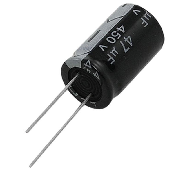
Electrolytic Capacitor
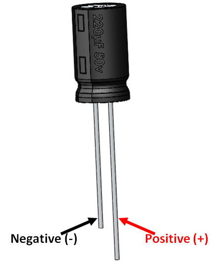
Electrolytic Capacitor Pinout Configuration
The Electrolytic Capacitors have polarity. Meaning they have a positive and negative pin. The pin which is long is the positive pin and the pin which is short is the negative pin. You can also identify the polarity using the negative strip on the capacitor label. As shown in the picture above the negative pin will be directly under the negative symbol.
Note: There are many types of capacitors; however electrolytic capacitors are the most widely used ones and this document is applicable only for the same.
Features
- Capacitor Type - Electrolytic
- Has a high range of capacitance value starting from 0.01uF to 10000uF
- Has a high range of voltage value starting from 16V to 450V
- Can withstand a maximum of 105°C temperature
Other types of Capacitors
Ceramic Capacitor, Box Capacitor, Variable Capacitor
Capacitor Parameters Selection
Ever wondered about the types of Electrolytic capacitors available in market and how to select one for your project? Electrolytic Capacitors can be classified based on two main parameters. One is their Capacitance(C-Farad) itself and the other is its Voltage (V-Volts) rating.
Capacitor is a passive component which can store a charge (Q). This charge (Q) will be a product of the value of capacitance (C) and the voltage (V) applied to it. The value of the capacitance and Voltage of a capacitor will be mentioned on its label.
Hence the amount of charge a capacitor can be found using the value of Voltage (V) and Capacitance (C) of the capacitor.
C = Q×V
Precaution
While using an Electrolytic capacitor care should always be taken to connect the positive pin to the positive of the circuit and the negative pin to the negative of the circuit. Also the voltage appearing across the capacitor terminals should always be less than the rated capacitor voltage (V). Failing to do so will lead to abnormal heating of the capacitor and might even burst.
Capacitor in series and parallel
In most of the circuits the value of the capacitance need not be exactly the same value specified in the circuit. A higher value of capacitance will generally not affect the performance of the circuit. However, the value of voltage should be the same or higher than the specified value to prevent the risk mentioned in precaution above. In that case, if you do not have the exact value you can use to capacitors in series or parallel to attain the desired value.
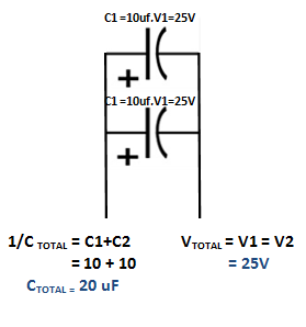
When two capacitors are connected in series then, the value of the capacitance(C) gets inversely added up and the rated voltage (V) is directly added up in series.
When two capacitors are connected in parallel then, the value of the capacitance(C) gets directly added up and the rated voltage (V) is remains the same in parallel as shown in the picture below.
Commonly Used Electrolytic Capacitors
Electrolytic Capacitors are not available in all desired values of Capacitance(C) and voltage (V). The most commonly available values are given in the table below
|
S.No: |
Commonly Available capacitor values |
||||
|
1 |
0.1uF – 16V |
0.1uF – 25V |
0.1uF – 50V |
0.1uF – 63V |
- |
|
5 |
0.22uF – 16V |
0.22uF – 25V |
0.22uF – 50V |
0.22uF – 63V |
- |
|
9 |
0.33uF – 16V |
0.33uF – 25V |
0.33uF – 50V |
0.33uF – 63V |
- |
|
13 |
0.47uF – 16V |
0.47uF – 25V |
0.47uF – 50V |
0.47uF – 63V |
- |
|
17 |
1uF – 16V |
1uF – 25V |
1uF – 50V |
1uF – 63V |
1uF – 450V |
|
22 |
2.2uF – 16V |
2.2uF – 25V |
2.2uF – 50V |
2.2uF – 63V |
- |
|
26 |
3.3uF – 16V |
3.3uF – 25V |
3.3uF – 50V |
3.3uF – 63V |
- |
|
30 |
4.7uF – 16V |
4.7uF – 25V |
4.7uF – 50V |
4.7uF – 63V |
- |
|
34 |
10uF – 16V |
10uF – 25V |
10uF – 50V |
10uF – 63V |
10uF – 450V |
|
39 |
22uF – 16V |
22uF – 25V |
22uF – 50V |
22uF – 63V |
- |
|
43 |
33uF – 16V |
33uF – 25V |
33uF – 50V |
33uF – 63V |
- |
|
47 |
47uF – 16V |
47uF – 25V |
47uF – 50V |
47uF – 63V |
- |
|
51 |
100uF – 16V |
100uF – 25V |
100uF – 50V |
100uF – 63V |
- |
|
56 |
220uF – 16V |
220uF – 25V |
220uF – 50V |
220uF – 63V |
- |
|
60 |
330uF – 25V |
- |
- |
- |
- |
|
61 |
470uF – 16V |
470uF – 25V |
470uF – 50V |
470uF – 63V |
- |
|
65 |
1000uF – 25V |
1000uF – 50V |
- |
- |
- |
|
67 |
2200uF – 25V |
2200uF – 50V |
- |
- |
- |
|
69 |
3300uF – 25V |
3300uF – 50V |
- |
- |
- |
|
71 |
4700uF – 25V |
- |
- |
- |
- |
|
72 |
10000uF – 50V |
- |
- |
- |
- |
Applications
- Filter circuits like High/Low pass filter etc.
- Remove noise from a circuit
- Smoothing ripples in converters
- Fading LED circuits
- Resonant circuits.


