Optimized at frequencies beyond traditional industry targets to support emerging applications
Understanding Zero Crossing Detectors: Fundamentals and Application

What is a Zero Crossing Detector?
A Zero Crossing Detector is an essential circuit widely used in signal processing and electronics to detect when an AC signal crosses zero volts, transitioning between positive and negative cycles. Its main function is to identify the precise moments when a waveform shifts its polarity, called the zero-crossing point. Zero-crossing detector circuits are integral in applications like phase-locked loops, motor control, and frequency detection.
Zero Crossing Detector Circuit
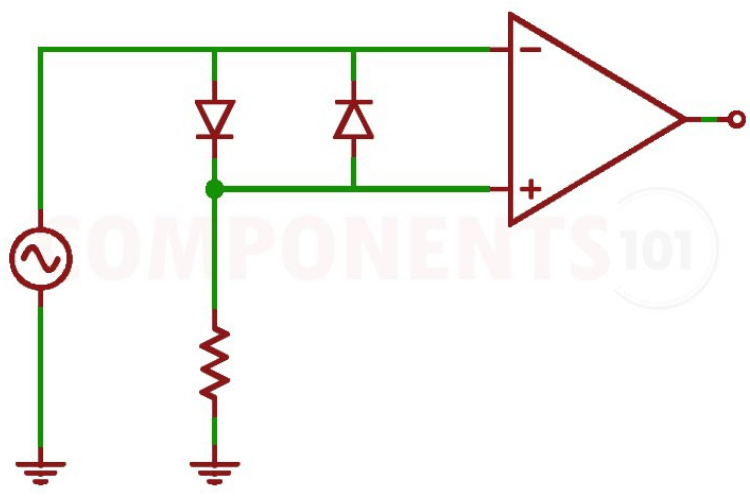
A typical zero crossing detector circuit is based on an operational amplifier configured as a comparator. The working of an op-amp based zero crossing detector is pretty simple. The op-amp compares the input signal with a reference voltage, which is usually set to 0V. When the input signal crosses zero, the output of the Op-amp will shift its output either from negative to positive or from positive to negative. It shifts negative to positive when the input signal changes polarity from positive to negative and vice versa. As a result, if we provide an AC signal as an input we will get a square wave output from the op-amp zero crossing detector. Here is a basic op-amp zero crossing detector circuit.
And here is the simulation of the same circuit.
As you can see the circuit is fed with a Sinewave signale. And when the input signal crosses 0V, the op-amp switches between its high and low output states, thus outputing a squarewave signal at the output.
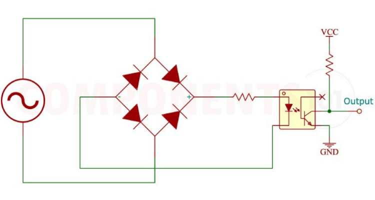
Similar to the op-amp based zero crossing detector we can also construct a zero-crossing detector using an optocouplor. Even though both are zero crossing detectors, both have different output characteristics. While an opamp based zero crossing detector outputs a squarewave like signal at the output, the optocoupler based one will only generate a breef pulse when the input signal is at zero level. To further understand, let’s look at the circuit diagram for the optocoupler based zero crossing detector.

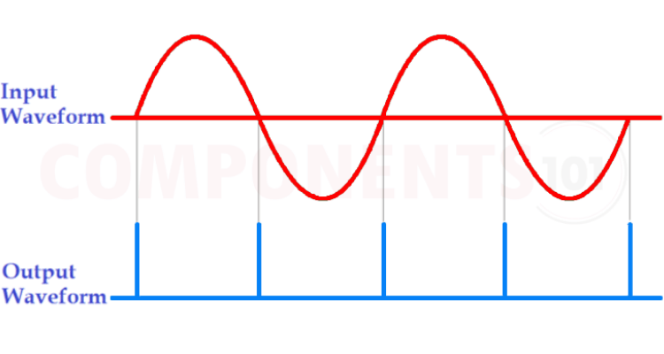
As you can see the input AC is connected to a bridge rectifier and the unfiltered output of the bridge rectifier is then connected to the optocoupler. Since we are using a bridge rectifier, all the pulses go to the optocoupler is with the same polarity. The emitter pin of the optocoupler is connected to the DC ground while the collector pini is pulled upto the VCC. Whenever the input voltage higher than that of the forward voltage of the optcouplers internal LED, the optocoupler will be in on state thus pulling the output to the ground. As soon as the voltage drops below the level, the optocoupler turns off, and thus a brief pulse appears at the output.

The above graphs show the illustration the input and output signal of the optocoupler based Zerocrossing detector. These type of zero crossing detectors are common in chea electronics products for traic driving as well as for frequency counting.
Applications of Zero Crossing Detectors
As we mentioned earlier the Zero crossing detectors has plenty of application in our everyday equipments. Here are some of them:
-
Phase Detection: Zero crossing detectors are used in phase-locked loops (PLL) to detect the phase of an AC signal.
-
Sine Wave to Square Wave Conversion: It can convert an AC sine wave into a square wave for easier digital processing.
-
Thyristor and Triac Control: Zero crossing detectors are used in light dimmers and motor control circuits to switch thyristors or triacs at the zero-crossing points to minimize electromagnetic interference.
-
Frequency Measurement: Zero crossing detectors can be used to measure the frequency of an AC signal by counting the zero crossings over a period.
-
Tachometers: Zero crossing detectors circuits can be used in speed sensors and tachometers to detect rotational speeds by measuring frequency changes.
-
Switching Power Supplies: In switch-mode power supplies, zero crossing detectors are used to synchronise the switching of components like MOSFETs or IGBTs with the input AC supply. This ensures that the switching occurs at the zero crossing of the AC voltage, minimising electromagnetic interference (EMI) and improving the efficiency of the power supply.
-
Audio Processing Applications: Zero crossing detectors are used in audio processing for tasks such as pitch detection, audio effect processing, and envelope detection.
Commonly Asked Questions About Zero Crossing Detectors
What is a Zero Crossing Detector (ZCD)?
A Zero Crossing Detector is a circuit that detects when an AC signal crosses the zero-voltage point (from positive to negative or vice versa) and outputs a signal indicating the event.
How does a Zero Crossing Detector work?
A Zero crossing detector monitors the input AC signal and generates a pulse whenever the signal crosses zero voltage. This pulse can be used for timing purposes, such as triggering other circuits at precise points in the AC cycle.
Why are Zero Crossing Detectors used?
Zero crossing detectors are used to synchronize electronic devices with AC power sources, reducing electrical noise and ensuring more efficient switching in devices like dimmers, motor controllers, and power supplies.
What are the benefits of using a Zero crossing detectors in power electronics?
The main benefits include minimizing electrical noise, reducing harmonic distortion, and allowing more precise control over switching devices like Triacs or Thyristors.
Can Zero Crossing Detectors be used with DC signals?
No, Zero crossing detectors are designed to work with AC signals, as they rely on detecting the transition through zero voltage, which only occurs in AC waveforms.
What is the difference between a Zero crossing detectors and a phase-locked loop (PLL)?
A Zero crossing detector detects zero-crossing points of AC signals to provide timing pulses, whereas a PLL is used to lock onto a signal’s phase and frequency. Zero crossing detector is a simpler circuit, while PLLs offer more precise frequency and phase control.
Are there any limitations of Zero Crossing Detectors?
Some limitations include sensitivity to noise near the zero-crossing point, which may cause false detections. Additionally, in fast-switching applications, they may not provide the timing precision needed without additional filtering or control.
How is noise handled in a Zero Crossing Detector?
To minimize noise, Zero crossing detector circuits often include filters or hysteresis to prevent false zero-crossing detections caused by noise around the zero point of the AC signal.


