

Optimized with highly sensitive cap touch sensors, extensive peripheral circuits and 125℃ operation
Solid State Relay - Basics, Working, Types and Applications of SSR
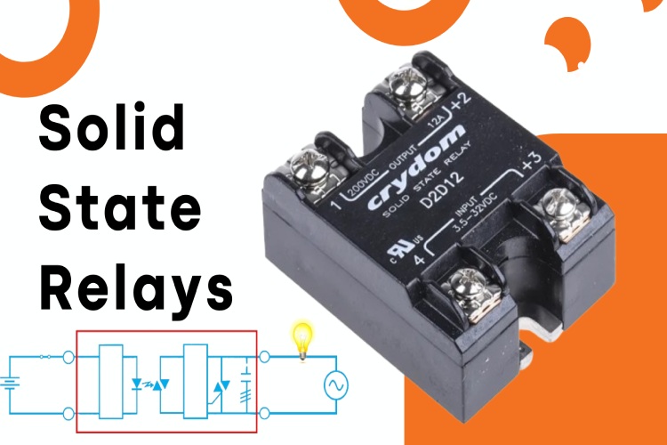
What is Solid State Relay?
A solid state relay or an SSR is an electronic switching device which can be controlled by applying an external voltage to the control terminals. If we consider function, they are very similar to the electromechanical relays we are familiar with. But the solid state relays don’t have any mechanical parts, instead, they use solid state devices such as triacs as switching elements. Solid state relays function as a switch without the need for any mechanical intervention.
Solid State Relay Working
As we know a conventional relay uses electromagnets, springs and mechanical contacts for switching. Unlike conventional relays, SSR uses the electrical and optical properties of solid-state semiconductors for the isolation and switching functions. Like a conventional electro-mechanical relay, SSR provides complete electrical isolation between its control and output terminals. When turned off, the SSR will have an almost infinite resistance between its output terminals, acting as a switch. When turn on, the resistance between the output terminals will be dropped to a very low value, almost negligible, acting as a short circuit path between terminals.
The above image is a simplified solid state relay circuit. It consists of an input and output circuit. The input side is connected to the output circuit through an optocoupler, thus giving isolation between the input and output sides. When the optocoupler is activated by applying a voltage in between the input terminal, the driver circuit in the output section also gets activated, thus turning on the output.
Types of Solid State Relay
Solid-state relays (SSRs) can be categorized into different groups based on various criteria such as the nature of the input control signal, the type of load they control, and their switching characteristics. Here are some common ways to group SSRs:
Based on Control Signal
- DC-Controlled Solid State Relays: These SSRs are activated by a DC control signal. They are commonly used in applications where the control signal originates from a DC source like a microcontroller or a DC switch. The below image shows the circuit diagram of a simple DC-controlled AC SSR.
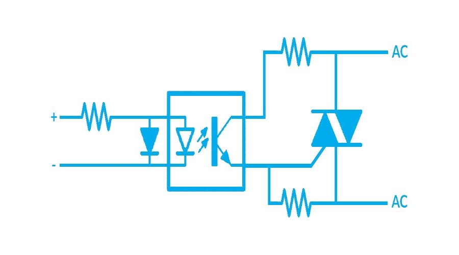
Here is a circuit diagram of a DC-controlled AC SSR.
- AC-Controlled Solid State Relays: These are activated by an AC control signal. They are suitable for applications where the control signal is derived from an AC source.
Based on the Load Type
- AC Solid State Relays: Designed for switching AC loads. These often use thyristors or triacs for controlling AC devices like heaters or motors. Within the AC solid state relays, you can find two types based on the number of phases it can control.
- Single-Phase Solid-State Relay: used to control single phase loads.
- Three Phase Solid State Relay: Used to control three-phase loads.
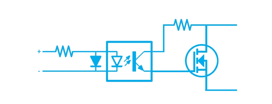
- DC Solid State Relays: Tailored for controlling DC loads, using semiconductor switches like MOSFETs.
Based on Switching Characteristics
- Zero Crossing Solid State Relays: Switch on or off when the AC load's voltage crosses zero. Ideal for resistive loads to minimize electrical noise and wear on the relay.
- Random Turn-On Solid State Relays: These SSRs can switch at any point in the AC cycle, allowing for more precise control, especially in phase angle control applications.
Based on Output Modulation
- Analog Switching Solid State Relays: Control the output power in proportion to the input signal. Useful in applications requiring variable power control.
- Time Proportioning Solid State Relays: Switch the load on and off at intervals proportional to the input signal, often used for temperature control.
Solid State Relay Application
Solid State Relays are widely used across various industries due to their reliability, long life, and fast switching capabilities. Here are some common Solid State relay Uses:
- Industrial Automation: SSRs are extensively used in automated manufacturing processes for controlling heaters, motors, and other machinery.
- Temperature Control: In applications like ovens, incubators, and HVAC systems, SSRs are used for precise temperature control.
- Lighting Control: SSRs are ideal for controlling lighting systems, including dimming controls in architectural and stage lighting.
- Motor Control: They are used in controlling electric motors, particularly where precise control or frequent switching is required.
- Pump Control: SSRs are employed in controlling pumps in various industrial and commercial applications.
- Power Regulation: In power supplies and voltage regulators, SSRs are used for managing power delivery efficiently.
- Home Appliances: Many modern appliances use SSRs for functions like temperature control in ovens, microwaves, and toasters.
- Medical Equipment: Reliability and precision make SSRs suitable for various medical devices, such as in incubators and diagnostic equipment.
- Automotive Applications: In electric vehicles and automotive electronics, SSRs are used for controlling lighting, battery management, and other electronic systems.
- Telecommunication Equipment: SSRs provide reliable switching solutions in telecommunications infrastructure.
Popular Solid State Relay Manufactures
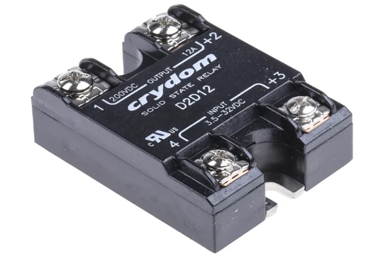
Some of the most popular manufacturers of Solid State Relays are Omron, Crydom, Siemens, Schneider Electric, Rockwell Automation (Allen-Bradley), Panasonic, Fotek, Carlo Gavazzi, IDEC, Phoenix Contact, Opto 22, and ABB.
Solid State Relays vs Electromechanical Relays
Here's a comparative table highlighting the key differences between Solid State Relays (SSRs) and Electromechanical Relays (EMRs):
| Feature | Solid State Relay (SSR) | Electromechanical Relay (EMR) |
| Switching Mechanism | Uses semiconductor devices like thyristors, triacs, or MOSFETs. | Uses physical contacts that open and close. |
| Switching Speed | Very fast (on the order of microseconds to milliseconds). | Slower compared to SSRs (milliseconds to seconds). |
| Lifetime | Longer, due to the absence of moving parts and mechanical wear. | Shorter, as mechanical parts wear out over time. |
| Noise | Silent operation as there are no moving parts. | Audible clicking sound due to the movement of mechanical parts. |
| Electrical Noise | Generates minimal electrical noise. | Can generate electrical noise due to arcing when contacts open/close. |
| Size | Typically, more compact. | Generally larger, especially for higher power ratings. |
| Heat Generation | Generates more heat under load, often requiring heat sinks. | Generates less heat, as contacts do not contribute significantly to heat. |
| Cost | Generally, more expensive than EMRs. | Usually less expensive than SSRs. |
| Load Type | Better for high-speed switching and precise control, especially with AC. | More versatile for various load types, including high-current applications. |
| Isolation | Provides good electrical isolation between control and load circuits. | Also provides electrical isolation but depends on the physical gap. |
| Sensitivity to Environment | Less sensitive to vibration and shock. | Sensitive to vibration and shock, which can affect mechanical contacts. |
| Voltage Drop | Typically has a small voltage drop across the switch. | Minimal voltage drops when contacts are closed. |


