Arduino UNO Q bridges high-performance computing with real-time control.
Selecting the Right Heat Sink for your Design – Steps for Heat Sink Calculation and Selection

For any electronics design, “Thermal Management” is the key element, which decides the optimal performance and efficiency of the system during its entire product life. This article will give more insights into the Selection and Design of Heat Sinks.
General Types of Heat Transfer
In thermal engineering, the Heat is transferred from higher temperature to lower temperature by the following 3 Ways-
Conduction: Heat Transfer happens because of the movement of molecules. Molecules at higher temperatures vibrate at a higher amplitude and pass the energy to the lower temperature molecules.
Convection: Heat transfer happens due to the bulk movement of fluids (air or liquid) from the hot surface to the cold surface.
Radiation: Heat transfer happens in the form of Electromagnetic radiation.
Most of the electronic device cooling systems use conduction and convection type heat transfer for thermal management.
How to Select or Design a Heat Sink for Your Application
In general, the following are the major Heat Sink Design Consideration factors for good selection and design of Heat Sinks.
- Device Operating Temperature Range (Ambient Temperature)
- System IP Rating
- Product Size
- System Cost
- Availability of Convection mode cooling options
- Insulation/Isolation Requirements
- Component Package
Now, if you want to select a Heat Sink for your application, the following steps will come in handy. We have considered the LM317 Voltage regulator as an example, but it can be of any other linear or switching component.
Step 1: Determine Power Dissipation by the Device:
The first step to determine the Heat Sink design is to determine how much power is dissipated from the Semiconductor device. There are different methodologies applied to calculate the Power Loss in the Semiconductor device. The below example provides information about how the device power dissipation can be calculated for Linear Power Supplies
For LM317, the designer wants to design the output Specification as 5V_0.5A for maximum input of 12V. The power dissipated by LM317 is (12-5) x 0.5 = 3.5W.
Step 2: Extract Datasheet Values:
The next step after obtaining the device power dissipation is extracting thermal resistance values from the LM317 datasheet.
The below table is extracted from ST LM317 and as per the recommended operating conditions, the maximum operating virtual junction temperature Tj = 125˚C. So under any operating conditions, the Tj should be managed below 125˚C.

After Obtaining the maximum junction temperature rating, it is important to determine the thermal resistance of the device. In order to determine the thermal resistance, we have to finalize which type of package is used for our design. If the designer is determined to use the TO-220 package, the Junction-to-ambient thermal resistance Rө(JA) = 50˚C/W.

So, without a heat sink, the maximum junction temperature can be calculated as-
Tj = Ta + Rө(JA) * Power
Ta = Ambient Temperature (Environment Temperature)
Let's take the system used here in the 35˚C ambient range.
Tj = 35 + (50 * 3.5) = 210˚C
As per the calculation, if the device is used without a heat sink, the maximum junction temperature of the device reaching 210˚C. This should be reduced below 125˚C and hence the Heat Sink should be used.
Heat Sink Calculation to Select the Right Type of Heat Sink
Based on the power dissipation and thermal data from the device manufacturer datasheet, we have found that whether the device can’t be operated without a Heat sink. In order to select the correct Heat sink, the following steps have to be done.
Step: 1 Determine Target Junction Temperature:
As per the datasheet Value, the maximum allowed Junction temperature is 125˚C. But, to improve efficiency and product lifetime, we can choose 80% of the max rating. So, the target Junction temperature can be 100˚C. (The target junction temperature rating varied based on the applications).
Step: 2 Determine Maximum Ambient Temperature:
Different electronics products will operate in different environments. Some systems will operate in fully air-conditioned units, some systems used in exposed open areas, and some of them placed near hot machinery. So, based on the environmental conditions, the designer has to identify and choose the system working environment conditions and choose the maximum ambient temperature. Here the LM317 is used in indoor applications and the maximum ambient temperature is taken as 35˚C.
Step: 3 Determine Required Thermal Resistance Value:
Based on the above results, the required thermal resistance of the whole system can be calculated using the below relation.
Rө(JA) = Tj – Ta / Pd
Rө(JA) = 100-35/3.5 = 18.57˚C/W
The Thermal Resistance Rө(JA) with Heat Sink Can be Given as-
Rө(JA) = Rө(JC) + Rө(CS) + Rө(SA)
Where-
Rө(JC) – Thermal Resistance Junction to Case - ˚C/W
Rө(CS) – Thermal Resistance Case to Heat Sink - ˚C/W
Rө(SA) – Thermal Resistance Heat Sink to Ambient - ˚C/W
Step: 4 Obtaining Junction to Case Thermal Resistance Value:
The below image provides details about the different sections of the semiconductor thermal system. The Rө(JC) can be obtained from the device datasheet (here LM317). For the LM317 - TO-220 package, the junction to case temperature is 5˚C/W.
![]()
Step: 5 Obtaining Case to Heat Sink (TIMs) Thermal Resistance Value:
The case to HeatSink thermal resistance values depends on the interface material used between Heat Sink and Electronic Device. The interface material is used to ensure the perfect connection between the Device and the Heat Sink by filling the air gaps and mechanical voids, irregularities, and provides better thermal conduction with or without electrical insulation.
The most commonly used thermal interface materials are thermal grease, thermal paste, mica, silicon pads, and phase change materials. The thermal resistance level of the thermal interface materials (TIMs) varies approximately between 0.2˚C/W to 2˚C/W based on the type of material, size, and thickness.
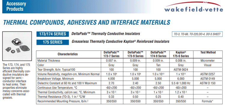
So, based on the application, insulation requirement, and required thermal resistance, the proper TIM materials can be selected. While selecting the thermal/silicon pads, proper dimensions, thickness, and fixture pressure levels have to be analyzed. In our application, let us take Wakefield-Vette – 173/174 series Deltapads thermally conductive insulators, which provide a maximum of 0.5˚C/W thermal resistance.
Step: 6 Obtaining Heat Sink Thermal Resistance Value:
From Step 3, we have found that the required total thermal resistance value for the designed application is 18.57˚C/W.
Rө(JA) = 18.57˚C/W

Rө(JA) = Rө(JC) + Rө(CS) + Rө(SA)
From Step – 4 and Step – 5 results-
18.57 = 5 + 0.5 + Rө(SA) => Rө(SA) = 18.57 – 5.5 = 13.07˚C/W
By considering a 20% margin, the maximum thermal resistance value of the selected heat sink should be below 10.5˚C/W.

Step: 7 Selection of Heat Sink for Natural Convection:
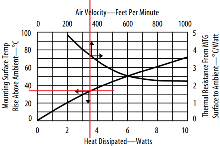
Based on the heat sink thermal resistance value of 10.5˚C/W, the Aavid – 7021 channel style heat sink with folded back fins have been selected and the thermal resistance value at natural convection (no forced air cooling) can be obtained from below manufacturer datasheet graph.

Source – Aavid – 7021 Channel style heat sink with folded back fins – Datasheet
Based on the above curve under natural convection for 3.5W, the temperature rise above ambient temperature using this heat sink is around 33˚C. The equivalent thermal resistance can be calculated as 33˚C/3.5W = 9.42˚C/W < 10.5˚C/W, which is satisfying our requirement.
LM317 Junction Temperature Calculation with Aavid 7021 Heatsink, Wakefield-Vette – 173-9 Series Deltapads TIM under natural air convection for 5V_0.5A output on max input of 12V is-
Tj = Ta + {(Rө(JC) + Rө(CS) + Rө(SA) * Pd}
Tj = 35 + {(5+0.5+9.42) * 3.5} = 87.22˚C
Step: 8 Selection of Heat Sink with Forced Air Convection (Conduction + Convection):
If the above system is placed in 55 square centimeter area enclosure and using 12 CFM cooling fan means the Air velocity in feet per minute is calculated by below relation-
55 Sq.Cm = 55/900 = 0.06 Sq.Feet
12CFM to FPM = 12/0.06 = 200 FPM
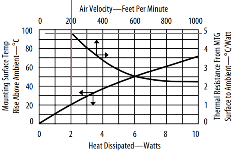
The thermal resistance of the Heat Sink located in 200 feet per minute Air velocity environment can be found in the below graph.

As per the above graph, the Thermal resistance of the Heatsink with 200FPM forced air cooling is given as 4.8˚C/W.
So, the Junction temperature of LM317 with forced air cooling can be found by the below relation.
Tj = Ta + {(Rө(JC) + Rө(CS) + Rө(SA) * Pd}
Tj = 35 + {(5+0.5+4.8) * 3.5} = 71˚C
From the above relations, it is found that the device junction temperature for a fixed power level is managed with proper selection of Heat sink with conduction and natural convection cooling mode. The performance can be further improved by adding a forced Air convection cooling system with conduction heat transfer.


