Optimized at frequencies beyond traditional industry targets to support emerging applications
What is a Load Cell & How Does it Work?

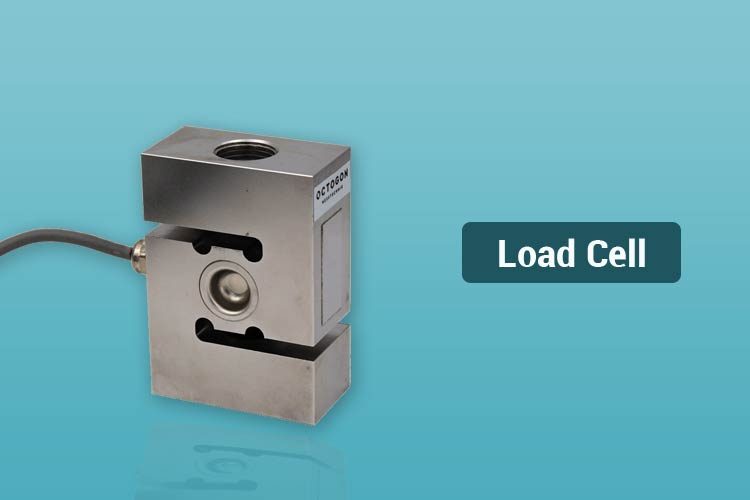
A load cell is a device that is used to measure force. In response to an applied force, it produces an electrical signal on the output. One of the most common types of load cell is the strain gauge, which is used to measure weight. In this article, we will take a look at how a load cell works and the various specifications of a load cell.
What Is a Load Cell?
A load cell is a force transducer. A transducer is a device that converts forms of energy into readable electrical signals. In this case, the load cell converts force to a voltage that can be read by an electrical device. One of the most commonly used load cells in daily life is the strain gauge, which can be found in almost all devices that measure weight.
How Does a Load Cell Work?
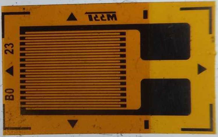
A load cell contains a very fine resistive material on a flexible backing. When a force is applied to the body of the load cell, the resistive material is forced to deform with the flexible backing. Since the dimensions of the resistive strip change, the resistance changes too.

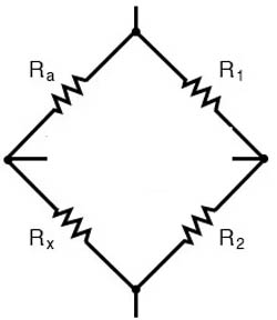
However, the change in resistance is very small compared to the total resistance of the material – typically in the range of 1:100. This makes absolute resistance measurement difficult. For this reason, the resistors formed by the resistive material on the flexible backing are placed in a configuration called a Wheatstone bridge. A Wheatstone bridge (named after Sir Charles Wheatstone, who popularized its usage) is a configuration of resistors in a diamond-like shape, with each side containing a resistor, as shown below.

A voltage called the excitation voltage is applied to two opposite corners of the diamond, and the output is read between the other pair of opposite corners. Normally, when no force is applied, all the resistors are of the same value. Each ‘leg’ of the Wheatstone bridge is a resistor divider, and since all the resistors are equal, the output voltages of each leg are equal – meaning that the output is 0V, since the output is in the middle of each voltage divider. When a force is applied, one of the resistors’ values changes, which changes the voltage on that leg of the bridge. This causes a small voltage difference to appear on the output.
Linked below is an interactive simulation for a Wheatstone bridge.
In the simulation, the bottom right resistor is varied between 9900Ω and 10100Ω, with a 10V excitation voltage, that gives ±25mV on the output.
How To Use a Load Cell?
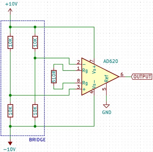
The output voltage of the load cell is very small and comes from a high-impedance source (the voltage dividers) – for this reason, some signal conditioning must be performed in order to read the voltage accurately. The signal conditioning circuit must have a high input impedance so as to not load the voltage dividers, and also have a high common-mode rejection ratio, since the absolute voltage at each leg is half the excitation voltage, and at the same time, have a high differential gain. This calls for an instrumentation amplifier, which fulfills all the conditions listed above. An example circuit is shown below using the AD620 configured with a gain of 100, meaning for every 1mV input voltage there will be a 100mV output. If the full-scale output of the bridge is ±25mV, for example, the output of the amplifier will be ±2.5V.

Conclusion
A load cell is a device used to measure force, based on a Wheatstone bridge. It creates a differential output, which can be measured using a differential amplifier.


