Arduino UNO Q bridges high-performance computing with real-time control.
How to Select Right Crystal Oscillator for your Microcontroller?

Oscillators play a crucial role in providing clock signals to microcontrollers, influencing their overall performance. Choosing the right oscillator is essential to ensure the desired functionality while considering factors like stability and cost. This article will explore various oscillator options and their advantages and disadvantages, enabling you to make informed decisions for your microcontroller applications. The following is the general categorization of oscillators for microcontrollers.
Internal Oscillators: Simplifying Clocking Solutions
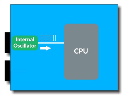
Internal oscillators, available within the microcontroller itself, offer convenience by eliminating the need for external components. While they lack precision and frequency stability, advancements have led to improved accuracy, typically ranging from ±20% to ±1.5% in newer microcontrollers. Internal oscillators can be calibrated at the factory or manually trimmed for specific applications, making them suitable for many scenarios.
CMOS Clocks: Leveraging Existing Clock Signals
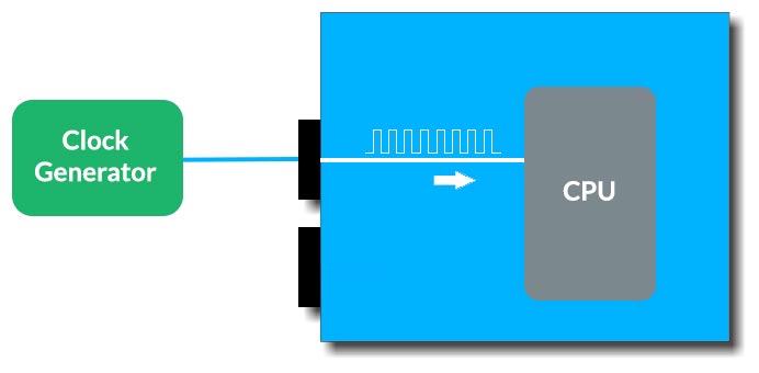
CMOS clocks refer to clock signals sourced from other components on the board. These clocks are viable options if their frequency and electrical characteristics align with the microcontroller's requirements. Two options for generating CMOS clocks are crystal oscillators and silicon oscillators. Crystal oscillators provide high precision and stability without the complexities associated with standalone crystals, while silicon oscillators offer versatility and reliability, albeit at a higher cost.
Quartz and Ceramic Oscillators: Precision and Cost Considerations
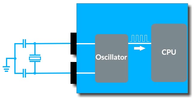
For applications demanding high precision and stability, standalone crystals are an excellent choice. With tolerances below 20 parts per million, these oscillators ensure accurate timekeeping. When selecting a crystal oscillator, the total load capacitance must be determined, considering the crystal's specifications and any parasitic capacitance. On the other hand, ceramic resonators offer a cost-effective alternative, even though offer lower accuracy (typically 1000 to 5000 parts per million) compared to crystals.
Key Points to consider when selecting an Oscillator.
Now that we have discussed the categorization, let’s look at some key points we must consider when selecting an oscillator.
Output Frequency
The primary characteristic of an oscillator is the frequency it generates. An oscillator is a device that accepts an input voltage (typically DC) and produces a repetitive AC output at a specific frequency. The required frequency depends on the system and its intended application. Certain applications necessitate low-frequency crystals in the kHz range, such as a watch crystal at 32.768 kHz. However, most modern applications require higher-frequency crystals ranging from less than 10 MHz to over 100 MHz.
Frequency Stability and Temperature Range
Frequency stability is determined based on the system requirements. It quantifies the frequency change caused by certain factors relative to the centre frequency.
Stability = Change in Frequency ÷ Center Frequency
For example, if an oscillator's output frequency is 10 MHz and it changes by 10 Hz due to temperature variations, its temperature stability would be 10/10,000,000 = 1×10-6 = 1ppm. Crystal oscillators typically exhibit stabilities ranging from 100ppm to 0.001ppm.
The desired frequency stability depends on the application and influences the type of crystal oscillator required. The operating temperature range is a significant factor in determining achievable stability.
Crystal Oscillator Types
- Simple Crystal Oscillator (XO):
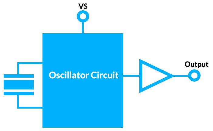
This basic type relies on the inherent characteristics of the quartz crystal resonator itself for stability. Higher-frequency quartz crystals, fabricated from a quartz bar, provide relatively stable frequencies despite ambient temperature variations from -55°C to +125°C (-67°F to +257°F). A properly cut quartz crystal can achieve stability of ±25ppm even within this wide temperature range. This represents a substantial improvement over passive resonators like LC tank circuits, which may vary by 1% or more (10,000ppm). However, some applications demand even better stability, requiring additional measures.
- Temperature Compensated Crystal Oscillator (TCXO):
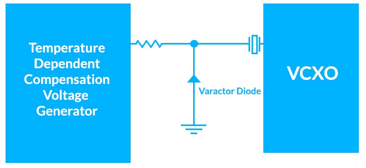
When the inherent frequency versus temperature stability of a quartz crystal is insufficient, a temperature-compensated unit, such as a TCXO, can be employed. TCXOs utilize temperature sensing devices and circuitry to generate a voltage curve that precisely cancels out the crystal's frequency drift over the temperature range. TCXO stability specifications typically range from less than ±0.5ppm to ±5ppm, depending on the type and temperature range.
- Oven Controlled Crystal Oscillator (OCXO):
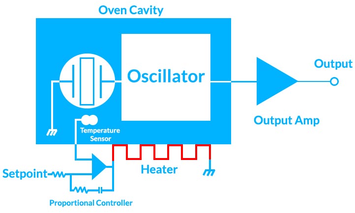
In cases where the stability of a TCXO is still inadequate, an OCXO may be necessary. OCXOs include an oven that heats the crystal to a controlled elevated temperature, ensuring stable crystal temperature despite wide ambient temperature variations. OCXOs provide significantly improved frequency versus ambient temperature stability by minimizing temperature variations. OCXOs can achieve stabilities as tight as 0.001ppm over the ambient temperature range. However, this enhanced stability comes with increased power consumption, as the oven requires power to maintain the temperature. Typical OCXOs may consume 1-5 W of power and require a warmup period after turning on to stabilize the temperature and frequency, which can range from 1 minute to over 10 minutes depending on the unit type.
- Voltage Controlled Crystal Oscillator (VCXO):
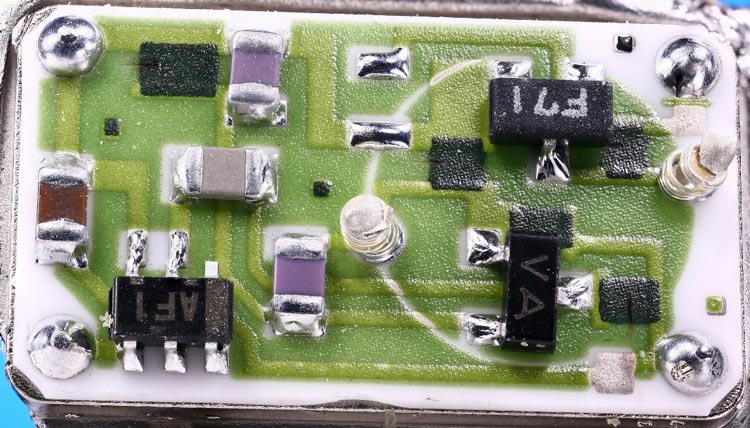
In certain applications, tuning or adjusting the oscillator frequency is desirable, such as for phase locking to a reference or waveform modulation. VCXOs provide this capability through an Electronic Frequency Control (EFC) voltage input. The tuning range for VCXOs varies from ±10ppm to ±100ppm or higher for specialized devices.
- TCVCXO and VCOCXO:
TCXOs and OCXOs often include an EFC input voltage, allowing precise adjustment to calibrate the output frequency.
Input Voltage and Power
Crystal oscillators can typically operate using a DC input supply voltage already available in the system. In digital systems, it is preferable to use a voltage matching the logic devices' voltage to ensure direct compatibility with logic levels. Common input voltages for digital units include +3.3 V or +5 V, while higher power output devices may employ higher voltages like +12 V or +15 V. Power consumption varies depending on the oscillator type, with XOs or TCXOs typically requiring a few milliamps, enabling operation below 0.01 W in low voltage systems. On the other hand, OCXOs may draw 5 W or 6 W during startup.
Output Waveform
The output waveform should be selected to match the load the oscillator drives in the system. Common outputs include CMOS for driving logic level inputs, which produces a square wave swinging between the ground and the Vdd rail of the system. For frequencies above 100 MHz, a differential square wave is often utilized, providing two outputs 180° out of phase with fast rise and fall times and minimal jitter. Popular types include LVPECL and LVDS. In cases where the oscillator drives RF components like mixers with a 50 Ω input, a specified sine wave output at a certain power level is required. Typical output power ranges between 0 dBm and +13 dBm (1 mW to 20 mW), but higher power outputs are possible if needed.
Package Size and Outline
The package size for a crystal oscillator varies depending on the oscillator type and specifications. Simple clock oscillators and some TCXOs can fit in compact packages as small as 1.2 x 2.5 mm. On the other hand, certain OCXOs may require larger packages, reaching dimensions of 50 x 50 mm or more for specialized designs. While larger through-hole packages like dual-in-line 4 or 14-pin types are still used for OCXOs or specific TCXOs, the majority of current designs employ surface mount packages. These surface mount configurations can be either hermetically sealed ceramic packages or FR-4-based assemblies with castellations for I/O connections.
When selecting a crystal oscillator, it's essential to consider various factors, such as available input voltages, the device driven by the oscillator's output, physical size constraints, and the operating environment. Additionally, specific applications may introduce additional specifications. By carefully considering these parameters, a crystal oscillator can be chosen to meet the requirements of a given system.


