Arduino UNO Q bridges high-performance computing with real-time control.
How does Input Impedance and Output Impedance Affect the Performance of an Operational Amplifier

When discussing about Operational Amplifiers, oftentimes we refer to the input impedance and output impedance of op-amp, both of which are important characteristics since they directly determine the performance of an amplifier and the types of loads, they can drive. In this article, let's discuss in detail, how these two parameters affect the operation of an op-amp and is it important to consider them during your circuit design.
Input Impedance in Op-Amp
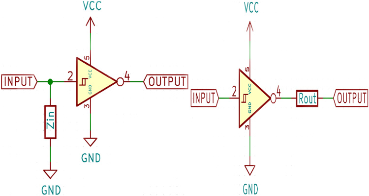
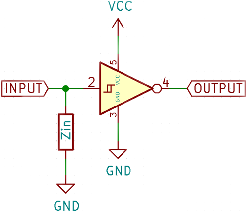
The input impedance of an ideal op-amp is assumed to be infinite, but this is not the case in real life. Every electrical input, source, or sinks a small amount of current. This can be modeled as a resistor connected parallel to the input as shown in the figure below.

In the above diagram, the input impedance is represented as a resistor, since in most cases this is true. However, the inputs have a small capacitance too. This is not a problem at lower frequencies since it only has the effect of decreasing the rise and fall times. However, at high enough frequencies, this capacitance can provide a significant load to AC signals and impede the rise and fall times which can also lead to signal distortion.
Output Impedance in Op-Amp
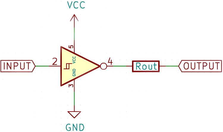
An ideal amplifier should be able to drive any amount of current into any load. This is possible with a powerful output driver stage, however, a bare amplifier by itself has some limitations in terms of how much current it can provide. For example, the common LM358 op-amp can source/sink only 40mA/20mA. This limitation in output drive can be thought of as a resistor in series with an ideal output as shown in the figure below.

Since the output is seen only at the other side of the resistor, if the output is loaded too much, there is a significant voltage drop across the resistor and the output is not the actual output provided by the amplifier. This can be countered by adding an output stage that amplifies the signal further and makes it suitable for driving large loads.
Effect of Input Impedance and Output Impedance on Amplifiers
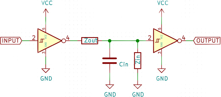
By themselves, these two problems can be overcome, but when you cascade amplifier stages, it begins to become a problem.

The output impedance of the first amplifier and the input impedance of the second amplifier together form a voltage divider, which attenuates the signal seen by the second amplifier. The input capacitance of the second amplifier and the output impedance of the first also act as a low pass filter and can filter out higher frequencies which may be undesirable.
Using the voltage divider concept, the formulas for the input and output voltages of an amplifier can be calculated given the gain, source impedance, and output impedance.
Vin = Vsource • (Zin/(Rs + Zin))
Where Vin is the input voltage the amplifier sees, Vsource is the input voltage, Zin is the input impedance, and Rs is the source impedance.
The output load voltage can be calculated similarly:
Vload = Vout • (Rload/(Rload + Zout))
Where Vload is the voltage across the load, Vout is the output of the amplifier, Rload is the load resistance, and Zout is the output impedance of the amplifier.
Vout can also be substituted with gain times input voltage.
The output impedance can also be calculated as a Thevenin equivalent circuit:
Zout = Vo/Is
Where Vo is the output voltage when the output is open circuit and Is is the output current when the output is shorted. This formula assumes a linear relationship between the output voltage and current.
Input and output impedance of amplifiers are a consequence of parasitic resistance and capacitance on the input and output. Formulas for the same are also provided. Knowing these limitations and how to overcome them leads to successful amplifier design.


