XBee S2C – RF Module
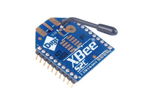
XBee S2C is a RF module designed for wireless communication or data exchange and it works on ZigBee mesh communication protocols that sit on top of IEEE 802.15.4 PHY. The module provides wireless connectivity to end-point devices in any ZigBee mesh networks including devices from other vendors. Please note that XBee is a module designed by ‘DiGi’ and ZigBee is the name of the protocol followed by XBee modules for establishing wireless communication. With a few of these modules the user can setup their own ZigBee network up-and-running in a matter of minutes.The XBee RF Module is compatible with other units that use ZigBee technology. These include other XBee modules, ConnectPortS gateways, XBee and XBee-PRO Adapters, XBee Sensors and other products that are designated with “ZB” product name.
XBee S2C Pin Configuration
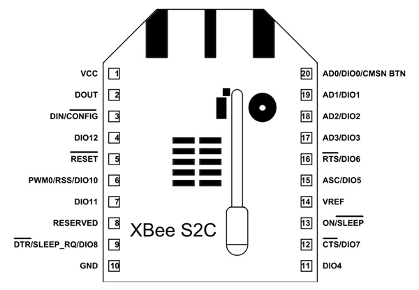
XBee S2C is a 20 pin module as given in XBee S2C pinout diagram and the description for each pin is given below.
|
Pin |
Name |
Description |
|
1 |
VCC |
Power supply |
|
2 |
DOUT/DIO13 |
UART data out pin (TXD)/GPIO |
|
3 |
DIN/CONFIG / DIO14 |
UART data in pin (RXD)/ GPIO |
|
4 |
DIO12/SPI_MISO |
GPIO/ Master Input-Slave Output pin of SPI interface |
|
5 |
RESET |
Module Reset pin |
|
6 |
RSS PWM /DIO10 |
RX Signal Strength Indicator pin / GPIO |
|
7 |
PWM1/DIO11 |
Pulse Width Modulator/GPIO |
|
8 |
RESERVED |
Do not connect |
|
9 |
DTR/SLEEP_RQ/ DIO8 |
Pin Sleep Control line /GPIO |
|
10 |
GND |
Ground |
|
11 |
DIO4/ SPI_MOSI |
GPIO/Master Output-Slave Input pin of SPI interface |
|
12 |
CTS/DIO7 |
Clear-to-send flow control/GPIO |
|
13 |
ON_SLEEP/DIO9 |
Device status indicator/GPIO |
|
14 |
VREF |
Voltage Reference for ADC |
|
15 |
ASC/DIO5 |
Associate Indicator/GPIO |
|
16 |
RTS/DIO6 |
Request to send flow control/ GPIO |
|
17 |
AD3/DIO3/SPI_SSEL |
Analog input/GPIO/SPI slave select |
|
18 |
AD2 /DIO2/SPI_CLK |
Analog input/GPIO/SPI clock |
|
19 |
AD1/DIO1/SPI_ATTN |
Analog input/GPIO/SPI attention |
|
20 |
AD0/DIO0/C |
Analog input/GPIO/ Commissioning button |
Features and Electrical Characteristics
- Transmission Frequency: 2.4GHz to 2.5GHz
- Number of Channels: 16 Direct Sequence Channels
- Featured with UART (250 Kb/s maximum) and SPI (5 Mb/s maximum) interface
- Featured with software adjustable transmitting power
- Indoor/Urban Range: 200ft
- Outdoor RF line-of-sight Range: up to 4000ft
- Transmit Power Output: 6.3mW (8dBm) in Boost mode,2mW (3dBm) in Normal mode
- RF Data Rate: 250,000 bps
- Receiver Sensitivity: -102dBm in Boost mode, -100dBm in Normal mode
- Supply Voltage Range: +2.1V to +3.6V
- Operating Current: 33mA (at3.3V, for Normal mode) , 45mA (at 3.3V,for Boost mode)
- Idle Current: 9mA
- Maximum output current on all pins together: 40mA
- Power-down Current: <1uA @25C
- ESD protection: 3000V
- Operating Temperature: -40ºC to 85° C
Note: Complete technical details can be found in the XBee S2C Module Datasheet linked at the bottom of this page.
Overview on the XBee S2C Module
A single XBee module does not have much use unless you already have a ZigBee mesh network up and running. So if there is no mesh network working you need at least two modules for establishing wireless communication and it is best to use a bunch of them to establish a mesh. This mesh could be implemented in applications like HOME AUTOMATION where all devices communicate with each other to give user most optimized performance. In the XBee HOME AUTOMATION the user can control all the home appliances through wireless and also setup task manager for switching appliances ON and OFF automatically at a given time.
How to use the XBee S2C module
First you need to know that XBee S2C module can be configured to work in three ways:
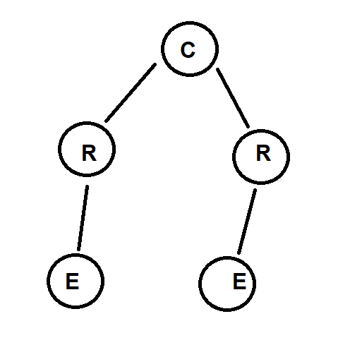
Coordinator- In any ZigBee network there will be a single coordinator device and it is a must. This device starts the network, selecting the channel and PAN ID. The host distributes addresses, allowing routers and end devices to join the network. The coordinator manages the other functions like secure the network and keep it healthy. This device cannot sleep and must be powered on at all times.
Router- The module configured as a router works as a node in the mesh. In a network there may be multiple routers. This device can join existing networks and send, receive, and route information. Routing involves acting as a messenger for communications between other devices that are too far apart to convey information on their own.Cannot sleep and must be powered on at all times.
End Device- A module configured as end device can join existing networks and send or receive information, but cannot act as messenger between any other devices.Always needs a router or the coordinator to be its parent device for it to work. The parent helps end devices join the network and stores messages for them when they are asleep.A ZigBee network may have any number of end devices. In fact, setting up a network with one coordinator and multiple end devices is possible. The end devices are mostly asleep until awoken.
The user has to configure each XBee module appropriately before setting up the mesh network to avoid failure. For configuring the module the user has to use X-CTU software developed by Digi International. The software can be downloaded for free here.
For setting up a simple communication network between two applications using XBee, you can just configure one module as coordinator and other as a router. After configuring you can connect the module to the microcontroller or arduino with a simple UART interface as given in circuit below. This goes for both ends.
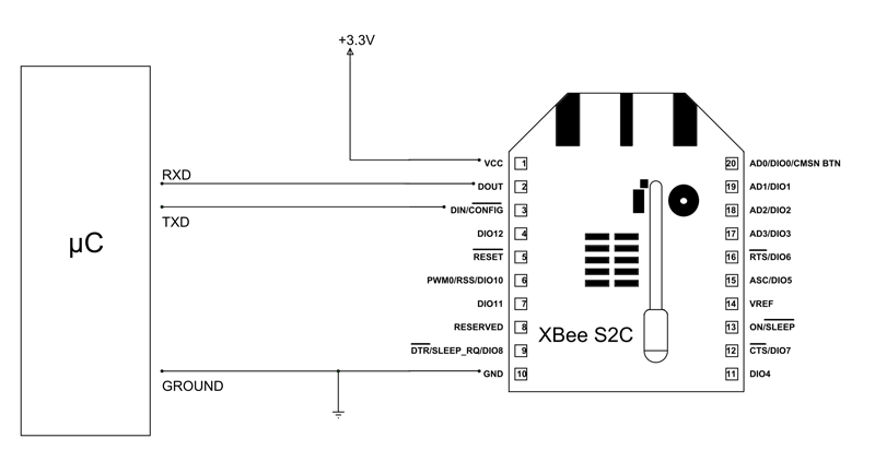
After setting up the circuit all you need to do is to program the applications at each end to exchange data from their respective XBee module.
Applications
- Home automation
- Commercial building automation
- Industrial application control
- Smart energy
- Medium range wireless communication
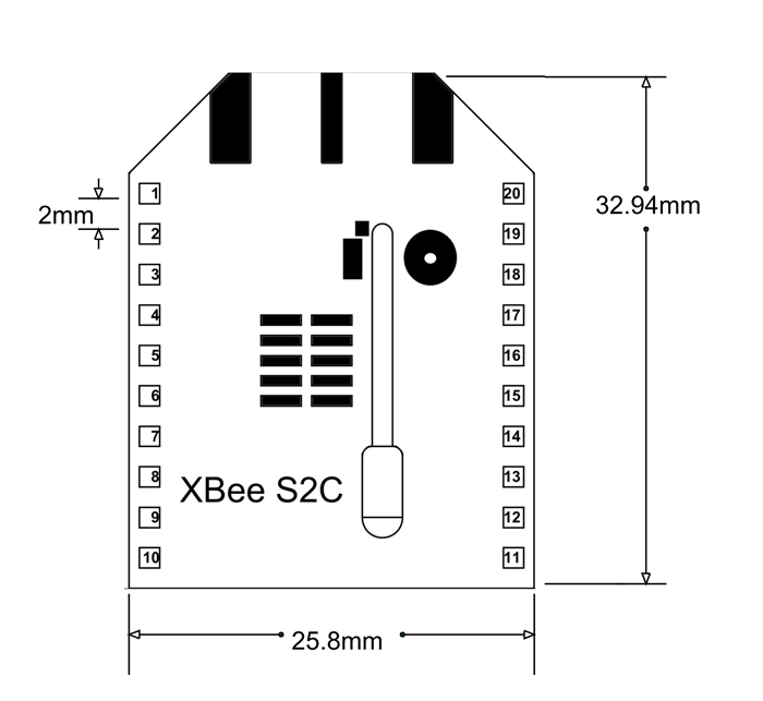
2-D Model and Dimensions
