BTA41-600B 40A 600V TRIAC Pinout, Specifications & Datasheet
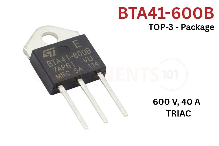
The BTA41-600B is a high-power, 40A bidirectional silicon alternating current switch (TRIAC) for heavy-duty industrial AC switching and phase control. Encapsulated in the rugged through-hole TOP3 power package, it combines an off-state repetitive peak blocking voltage of 600V (VDRM / VRRM) with a continuous RMS on-state current capacity of 40A (IT(RMS) at Tc = 80°C) and a high non-repetitive surge peak current rating of 400A (ITSM for a 20 ms half-sine cycle).
BTA41-600B Pinout Configuration
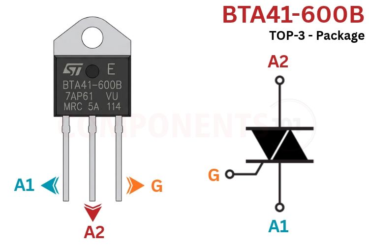
The BTA41-600B is housed in the 3-lead through-hole TOP3 insulated package. Looking directly at the front branded face of the device with the terminal leads pointing downwards, the pinout configuration is structured as follows.
| Pin Number | Pin Name | Terminal Type | Functional Description |
| 1 | A1 (MT1) | Main Terminal 1 | First main power terminal. Serves as the reference potential for gate triggering and snubber returns. |
| 2 | A2 (MT2) | Main Terminal 2 | Second main power terminal. Connected in series with the AC mains supply and high-power load. |
| 3 | G (Gate) | Control Terminal | Gate trigger terminal. Injecting trigger current relative to A1 fires the TRIAC into bidirectional conduction. |
| Tab | Isolated Tab | Heatsink Mounting Tab | Internally insulated ceramic mounting tab rated to 2500V RMS. Can be safely bolted to grounded heatsinks. |
*Note: In the BTA41 insulated version, the mounting tab has no electrical continuity with Pin 1, Pin 2, or Pin 3. In the non-insulated BTB41 version, the metal tab is electrically live and tied directly to Terminal A2.
BTA41 Series Package & Voltage Variants
The BTA40, BTA41, and BTB41 product family provides multiple package configurations and blocking voltage options to suit distinct thermal and electrical installation requirements.
| Part Number | Voltage Rating (VDRM / VRRM) | Package Type | Tab Isolation | Thermal Resistance (RθJC) | Delivery Mode |
| BTA41-600B | 600V | TOP3 Insulated | 2500V RMS (Insulated) | 0.9°C/W | Plastic Tube (30 pcs/tube) |
| BTA41-800B | 800V | TOP3 Insulated | 2500V RMS (Insulated) | 0.9°C/W | Plastic Tube (30 pcs/tube) |
| BTB41-600B | 600V | TOP3 Non-Insulated | Non-Insulated (Tab = A2) | 0.6°C/W |
Plastic Tube (30 pcs/tube) |
| BTB41-800B | 800V | TOP3 Non-Insulated | Non-Insulated (Tab = A2) | 0.6°C/W |
Plastic Tube (30 pcs/tube) |
| BTA40-600B |
600V |
RD91 Chassis Mount | 2500V RMS (Insulated) | 0.9°C/W |
Bulk Industrial Pack |
*Note: The suffix 'B' signifies standard 4-quadrant gate sensitivity with a maximum trigger current IGT of 50 mA across Quadrants I, II, and III, and 100 mA in Quadrant IV.
BTA41-600B Key Features & Specifications
- Device Polarity & Category: High-Power Bidirectional AC Switch (Standard 4-Quadrant TRIAC)
- Repetitive Peak Off-State Voltage (VDRM / VRRM): 600 V (Tj = -40°C to +125°C)
- Non-Repetitive Surge Peak Off-State Voltage (VDSM / VRSM): 700 V (tp = 20 ms, Tj = 25°C)
- RMS On-State Current (IT(RMS)): 40 A (full sine wave, 180° conduction angle, Tc = 80°C)
- Non-Repetitive Surge Peak On-State Current (ITSM): 400 A (tp = 20 ms) / 420 A (tp = 16.7 ms, Tj init = 25°C)
- I2t Value for Fusing: 1000 A²s (tp = 10 ms half-cycle)
- Critical Rate of Rise of On-State Current (dI/dt): 50 A/µs (IG = 2 x IGT, tr ≤ 100 ns, f = 120 Hz, Tj = 125°C)
- Gate Trigger Current (IGT) Quadrants I - II - III: 50 mA max (VD = 12V, RL = 33 Ω, Tj = 25°C)
- Gate Trigger Current (IGT) Quadrant IV: 100 mA max
- Gate Trigger Voltage (VGT): 1.3 V max (VD = 12V, RL = 33 Ω, Tj = 25°C)
- Gate Non-Trigger Voltage (VGD): 0.2 V min (VD = VDRM, RL = 3.3 kΩ, Tj = 125°C)
- Holding Current (IH): 80 mA max (IT = 500 mA, gate open)
- Latching Current (IL) Quadrants I - III - IV: 70 mA max (IG = 1.2 x IGT)
- Latching Current (IL) Quadrant II: 160 mA max
- Critical Rate of Rise of Off-State Voltage (dV/dt): 500 V/µs min (VD = 67% VDRM, gate open, Tj = 125°C)
- Critical Rate of Decrease of Commutating Voltage ((dV/dt)c): 10 V/µs min (at (dI/dt)c = 20 A/ms, Tj = 125°C)
- Peak On-State Voltage Drop (VTM): 1.55 V max (at ITM = 60 A, tp = 380 µs, Tj = 25°C)
- Thermal Resistance, Junction to Case (Rth(j-c)): 0.9°C/W (AC conduction, BTA41 TOP3 insulated)
- Internal Electrical Isolation Voltage (VISOL): 2500 V RMS (1 minute duration, UL1557 certified)
- Operating Junction Temperature Range (Tj): -40°C to +125°C
- Storage Temperature Range (Tstg): -40°C to +150°C
*Note: Complete Technical Details can be found in the BTA41-600B datasheet given at the end of this page.
BTA41-600B Equivalent & Alternative Components
| Equivalent Part | Max VDRM | Max IT(RMS) | Gate Sensitivity (IGT) | Package | Package |
| BTA41-800B | 800V | 40 A | 50 mA | TOP3 Insulated | Identical form factor; higher 800V breakdown voltage for heavy industrial 400V grids. |
| BTB41-600B | 600V | 40 A | 50 mA | TOP3 Non-Ins. | Non-isolated version; offers lower thermal resistance (0.6°C/W) for high-dissipation systems. |
| BTA40-600B | 600V | 40 A | 50 mA | RD91 Chassis | Heavy chassis module with screw terminals; ideal for high-vibration industrial cabinets. |
| Q6040J7 | 600V | 40 A | 50 mA | TO-218X Ins. | Littelfuse Teccor alternistor / standard TRIAC; widely available drop-in equivalent. |
| T4050-600B | 600V | 40 A | 50 mA | TOP3 Insulated | STMicroelectronics Snubberless series TRIAC with enhanced (dI/dt)c commutating immunity. |
| BTA16-600B | 600V | 16 A | 50 mA | TO-220AB Ins. | Smaller 16A insulated TRIAC for domestic appliances and lower power sub-3 kW loads. |
Brief Description of BTA41-600B
The BTA41-600B is a monolithic multi-layer semiconductor device functionally analogous to two inverse-parallel silicon controlled rectifiers (SCRs) integrated onto a single silicon chip with a single shared gate terminal. This configuration permits bilateral conduction in response to positive or negative gate trigger signals, enabling full-wave alternating current control without requiring bridge rectifiers.
When connected across an AC line, the device blocks voltage in both polarities until a current pulse exceeding the gate trigger threshold (IGT = 50 mA) is applied between the Gate and Terminal A1. Once triggered, the internal regenerative thyristor structure enters deep saturation within 2 microseconds, reducing the terminal voltage to a low forward drop (VTM ≤ 1.55V at 60A peak). Conduction continues until the AC load current naturally falls below the holding current threshold (IH = 80 mA) during the mains zero-crossing, at which point the TRIAC commutates OFF unless re-triggered in the subsequent half-cycle.
A critical engineering aspect of deploying standard 4-quadrant TRIACs on inductive loads (such as induction motors, transformers, and contactor coils) is commutation dv/dt. Because the load current lags the supply voltage in an inductive circuit, the TRIAC turns off when the current crosses zero, but a large instantaneous voltage already exists across the AC mains. This produces a steep rate of rise of reapplied off-state voltage ((dV/dt)c). If this voltage rate of rise exceeds the device's commutating limit (10 V/µs), residual charge carriers stored in the silicon junction will immediately re-trigger the TRIAC into unwanted conduction, resulting in complete loss of gate control. To prevent this, standard TRIAC circuits include an external RC snubber network (typically 39 Ω and 10 nF) shunting terminals A1 and A2.
The standout feature of the BTA41 is its 2500V RMS ceramic isolation barrier. In conventional power packages, the mounting tab is electrically shorted to the central terminal (A2). Under 230V AC mains operation, touching an uninsulated heatsink poses an immediate electrocution hazard, necessitating mica insulating wafers, thermal pads, and plastic mounting bushes that add thermal resistance and complicate automated assembly. The BTA41 incorporates an internal alumina ceramic substrate between the silicon die and the copper baseplate. This delivers certified 2500V RMS isolation while maintaining a low junction-to-case thermal resistance of just 0.9°C/W, providing maximum operator safety and thermal efficiency.
BTA41-600B Datasheet
Download the official manufacturer datasheet for the BTA41-600B 40A Standard TRIAC.
Applications
- Solid-State Relays (SSRs): High-reliability 40A solid-state AC relays replacing noisy, wear-prone mechanical contactors in industrial control panels.
- Industrial Heating & Ovens: Precision temperature control in commercial kilns, injection molding machines, bakery ovens, and electric boilers up to 9.2 kW.
- Commercial Water Heaters: Rapid, silent electronic thermostat switching for tankless domestic and commercial water heating elements.
- Heavy AC Motor Speed Control: Variable voltage phase control for ventilation fans, industrial blowers, and high-volume water pump motors.
- Resistance Spot Welding Machines: Primary AC transformer firing in automotive and metal fabrication spot welders.
- Soft-Starters for Induction Motors: Limiting mechanical shock and peak electrical grid inrush current when starting heavy induction machinery.
- High-Power Stage & Architectural Lighting: Full-range phase-fired light dimmers for high-wattage halogen and theatrical floodlight systems.
2D Model and Component Dimensions
The physical dimensions for the standard TOP3 Insulated package (from the official STMicroelectronics datasheet) are provided below:
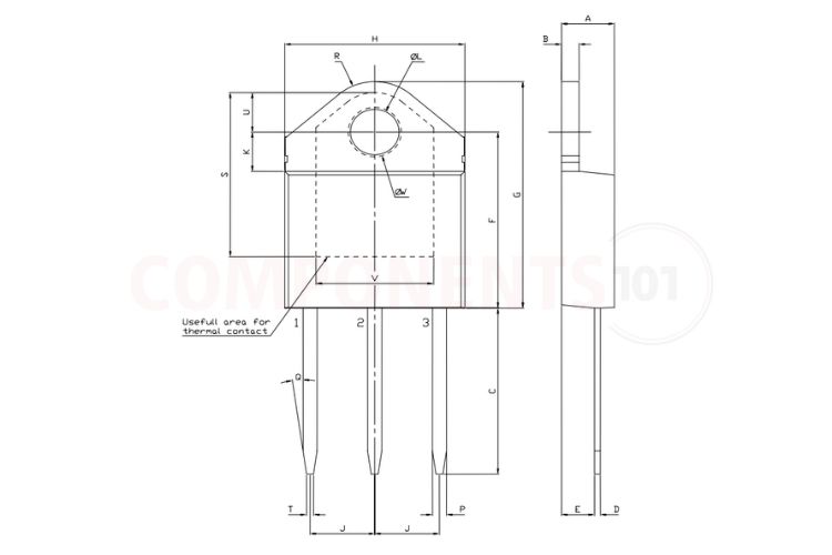
| Dimension Parameter | Symbol | Min (mm) | Typ (mm) | Max (mm) | Min (Inches) | Max (Inches) |
| Package Body Thickness | A | 4.40 | - | 4.60 | 0.1732 | 0.1812 |
| Mounting Tab Thickness | B | 1.45 | - | 1.55 | 0.0570 | 0.0611 |
| Package Body Height | C | 14.35 | - | 15.60 | 0.5649 | 0.6142 |
| Lead Thickness | D | 0.50 | - | 0.70 | 0.0196 | 0.0276 |
| Body Depth from Standoff | E | 2.70 | - | 2.90 | 0.1062 | 0.1142 |
| Total Body Width | F | 15.80 | - | 16.50 | 0.6220 | 0.6497 |
| Total Height Including Tab | G | 20.40 | - | 21.10 | 0.8031 | 0.8308 |
| Upper Body Width | H | 15.10 | - | 15.50 | 0.5944 | 0.6103 |
| Lead Pitch (Pin 1 to 2, 2 to 3) | J | 5.40 | - | 5.65 | 0.2125 | 0.2225 |
| Hole Center to Top Edge | K | 3.40 | - | 3.65 | 0.1338 | 0.1438 |
| Mounting Hole Diameter | ØL | 4.08 | - | 4.17 | 0.1606 | 0.1642 |
| Lead Width | P | 1.10 | - | 1.30 | 0.0430 | 0.0510 |
| Lead Length | R | - | 4.60 | - | - | 0.1811 |