TYN612 -Thyristor
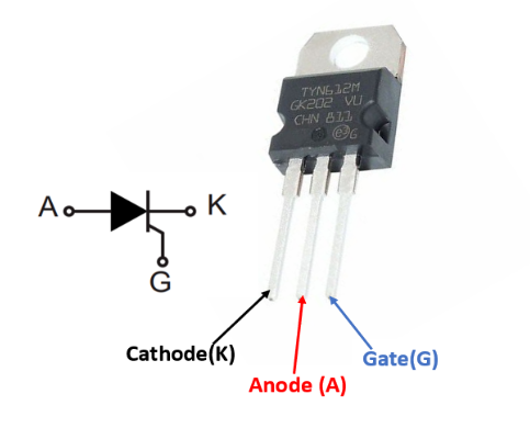
Pin Configuration
|
Pin NO. |
Pin Name |
Description |
|
1 |
K |
Cathode of Thyristor |
|
2 |
A |
Anode of Thyristor |
|
3 |
G |
Gate of Thyristor, used for triggering |
Features of TYN612- Thyristor
- On-state RMS current is 12 A
- Repetitive peak off-state voltage is 600 V
- Triggering gate current ranges from 5 mA to 15 mA
- Used as protection circuits, current limiting circuit and control circuits
- Provide optimized performance in a limited space
- Available in surface-mount and through-hole package
Technical Specification
- Dynamic resistance: 30mΩ
- I2t value for fusing: 98 A2S
- Maximum peak reverse gate voltage: 5v
- Peak gate current: 4A
- Operating temperature range: - 40 to + 125 °C
- Storage temperature: - 40 to + 150 °C
Note: Complete technical information can be found in the TYN612 Datasheet Linked at the bottom of this page.
TYN612 Equivalent Thyristors
TN1215, TYN612, TYN812, TYN1012
Where to use TYN612- Thyristor?
Thyristor is a switching device but can be used in power control circuit, over-voltage protection, and many other application. It requires a gate pulse to start, it gets self-latched and stays ON until the supply get interrupted. For this, we have to use a switching circuit in connection with the main supply of the circuit or across the thyristor to turn it OFF. Here, in the name TYN612, ‘6’ represents the value of Repetitive peak off-state voltage which is 600 V and ‘12’ represents the value of On-state RMS current which is 12 A. Thyristor TYN612 is fit for all modes of control like overvoltage crowbar protection, motor control circuit, inrush current limiting circuits, capacitive discharge ignition and voltage regulation circuits.
How to use TYN612- Thyristor?
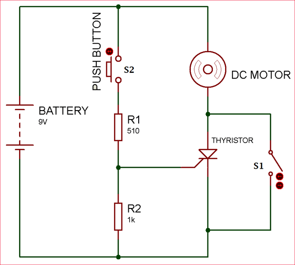
Initially, the switch S1 and S2 remains in normally-open state. When the supply ON, Thyristor remain reversed biased until the gate pulse provided. For providing gate pulse we have used Push Button S2. As the S2 switch close, thyristor turns ON and latch even we release the push button S2.
When the Thyristor has self-latched into the ON state, the only way to stop the Thyristor from conducting in this circuit is to interrupt the supply across the Thyristor. For that, we use switch S1, which short-circuit the anode and cathode, due to which the holding current get decreased to its threshold value. Therefore, Thyristor gets reset or turns OFF.
Resistance R1 used to provide sufficient gate current to turn ON the thyristor. Resistance R2 is used for decreasing the gate sensitivity and increase the dv/dt capability. Therefore, it prevents Thyristor from false triggering.
Application of TYN612- Thyristor
- Power Control
- Switching
- Zero voltage switching
- Over-voltage protection
- Pulse circuit
- Battery Charging regulator
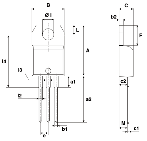
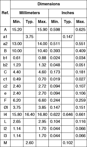
2D-model of TYN612- Thyristor