2N5401 PNP Transistor
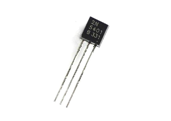
2N5401 is a PNP transistor designed specifically for high voltage - low power switching applications and amplifications. The NPN complementary for the device is 2N5551 and is available in TO-92, SOT54.
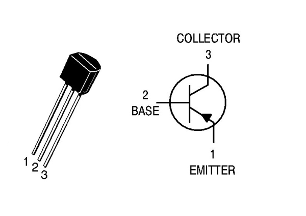
Pin Configuration
2N5401 has three pins like any other transistor namely EMITTER, BASE and COLLECTOR.
|
Pin |
Name |
Function |
|
1 |
Emitter |
Current flows in to the device through this pin |
|
2 |
Base |
Base is used for triggering transistor ON and OFF |
|
3 |
Collector |
Current flows out of this pin |
2N5401 Features and Electrical characteristics
- Available in Pb−Free package
- High collector breakdown voltage
- With DC Current Gain (hFE) up to 100
- Maximum voltage across collector and emitter: 150V
- Maximum current allowed trough collector: 600mA
- Maximum voltage across collector and base: 160 V
- Maximum voltage across base and emitter: 5V
- Operating temperature range: -55ºC to +150ºC
- Maximum power dissipation : 0.62 W
Similar Transistors
2N5551 (NPN), MPSA92, MPSA93, BF723, 2N5096
2N5401 Transistor Overview
2N5401 is specifically designed to be used in high voltage applications where load consumes very less power (i.e. Current drawn by load is low). These types of circuits can be seen in telephone systems. It can also be used when you want a simple switching device for high voltage loads. Also the component is cheap and easy to work with.
How to Use 2N5401 Transistor?
2N5401 can be used like any general purpose PNP transistor but for sake of understanding the device working let us consider a simple application circuit as shown below.
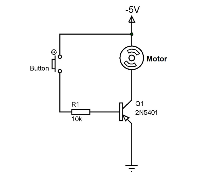
In the above circuit we are using 2N5401 as a simple switching device and the switching load being small DC motor. The button here is for providing the trigger to the transistor and 10KΩ resistor is for limiting the current to base and to avoid breaching maximum voltage allowed at the base. Also as pointed in the comment section belwo, considering the low gain of this transistor, it might be a better idea to use a low value resistor like 100R for R1 to allow more base current. The circuit is powered from a negative voltage source of -5V DC as shown in diagram.
Before going for working let us revise the typical characteristics of a PNP transistor:
- The device does not conduct when the current does not flow out of the base of the transistor or the device conducts only when the base current that flows out of the device reaches a threshold.
- The current flow through collector is determined by the base current to a certain point. So with higher the gate current we have lower conduction resistance and higher the collector current.
- The PNP transistor conducts only when a threshold current flows out the base, so the instant the base current reaches zero the device stops conducting.
Consider the button is not pressed: When the button is not pressed there will be no base current and with no base current the transistor will not conduct based on the characteristics of PNP transistor. When the transistor does not conduct the entire voltage appears across it and the motor will be OFF.
Consider the button is pressed: When the button is pressed, the base of 2N5401 will be connected to negative power supply and so there will be a path for the current flow. When the base current flows out from the device it will start conducting as stated in characteristics. In the presence of this collector current flow a voltage appears across the motor connected in series with collector pin. In the presence of the voltage the motor will start rotating and it will stay like that until the button is released. The moment the button is released the base current will reaches zero, there by turning OFF the transistor and the motor.
In this way we can turn motor ON and OFF by using simple button as a trigger and 2N5401 as switching device. In high speed switching the trigger is provided by microcontroller instead of button.
Applications
- General purpose switching and amplification
- Telephony applications
- High voltage application
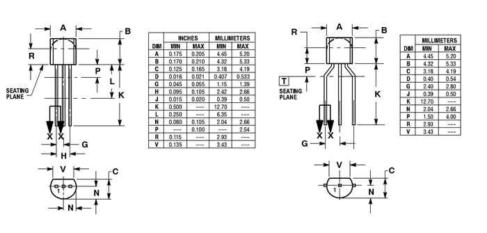
2D-Model


Example Circuit
A 10K resistor will only allow less than 50 micro-amps base current in your example. With a max gain of 100 you will have no more than 50 milliamps to turn the motor.
The transistor can pass up to 600mA (requires 6mA base current at hFe 100) but if switching a motor you probably want enough base current to achieve saturation, so let's say 20mA. That would be a 250R resistor rather than 10K and I would say that's pretty conservative and use 100R instead.