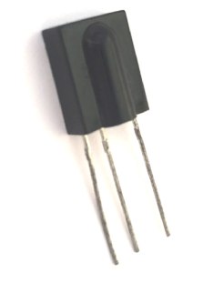
TSOP1738 IR Receiver
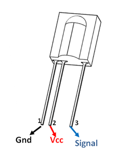
TSOP1738 Pin Configuration
|
Pin Number |
Pin Name |
Description |
|
1 |
Ground |
Connected to the Ground of circuit |
|
2 |
Vcc |
Typically connect to +5V, maximum of 6V can be given |
|
3 |
Signal |
The signal pin gives out the sequence based on the IR signal detected |
TSOP-1738 Characteristics
- Minimum and Maximum Input Voltage is -0.3 and 5V respectively. Typically +5V is used.
- Can detect IR signals from Remotes (38kHz)
- Operating current: 5mA
- High Range and wide coverage area.
- Will respond only to IR signals, due to high immunity against ambient light
- Low power consumption
- Has in-built pre amplifier
- TTL and CMOS compatible
Note: Complete Technical Details can be found in the TSOP1738 datasheet given at the end of this page.
TSOP1738 Equivalent IR Receivers
SM0038, TSOP-17XX
Where to use TSOP-1738 Sensor
The TSOP sensor has the ability to read the output signals from home remotes like TV remote, Home theatre remote, AC remote etc. All these remotes will work with a frequency of 38kHz and this IC can pick up any IR signals process them and provide the output on pin 3. So if you are looking for a sensor to analyse, re-create or duplicate the functions of a remote then this IC will be the perfect choice for you.
Also keep in mind that this series TSOP-1738 will receive only 38Khz IR signals. All remotes in India will operate in 38Khz, kindly ensure if it is the same in your country.
How to test and use TSOP-1738 Sensor
The TSOP-1738 is an IR Receiver Sensor, which can be used to receive IR signals of 38Khz. The sensor operates on 5V and consumes around 5mA to operate. Normally the signal pin (pin 3) IC is connected to a microcontroller to analyse the IR signal received. But let’s consider that you just purchased the IC and you want to check it is working. To do those just connect your TSOP as shown in the test circuit below
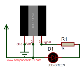
Now use any IR remote that’s lying around in your home and press any button on it. You should notice the Green Led blinking each time you press any button. This is just to ensure that the sensor is working as it has to be. Now, you can proceed with any MCU or MPU to decode the received IR signal. Once the IR signal is decoded, you can re-create it using an IR Blaster.
TSOP-1738 Applications
- Receive IR signals
- Decode Remote signals
- Analyse, re-create or duplicate remote Signals
- Wireless control applications
- Receiver circuit for IR remote controls
- IR Remote tester circuits
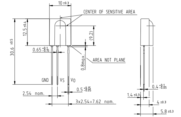
2D model of the component