RCWL0516 Microwave Distance Sensor Module
The RCWL0516 Microwave distance sensor uses microwave frequencies in a simple implementation of a Doppler radar. The circuitry inside the chip processes the signal and outputs an analog voltage that is proportional to the distance between the object and sensor.
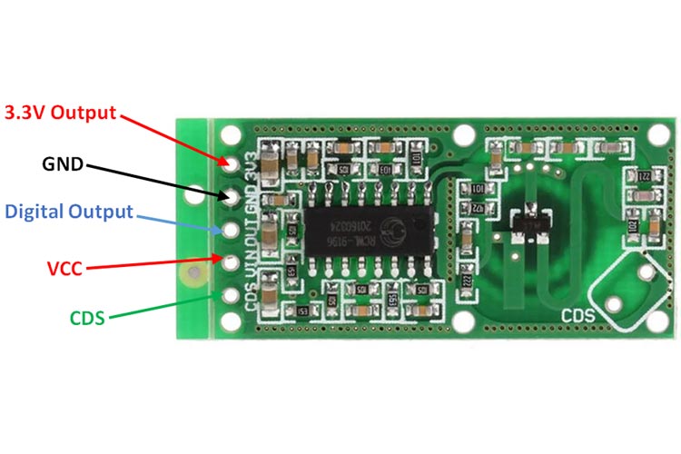
RCWL0516 Module Pin Description
|
Pin Number |
Pin Name |
Description |
|
1. |
3V3 |
Regulated 3.3V output |
|
2. |
GND |
Ground reference for module |
|
3. |
OUT |
Analog output from the sensor |
|
4. |
VIN |
Voltage input for the module |
|
5. |
CDS |
Sensor Disable |
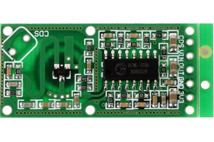
Components Present on the RCWL0516 Module
The following are the major components present in the module, which will be described later in the article.
RCWL0516 IC, transistors, capacitors, and resistors.
RCWL0516 Module Specifications
- Input Voltage – 4V to 28V
- Operating current – 3mA (max.)
- Operating frequency – 3.2GHz
- Transmission power – 30mW (max.)
- Regulated output voltage – 3.3V, max. 100mA
- Sensing distance – 5 to 7 meters
Note: Complete technical details can be found in the RCWL-0516 Datasheet linked at the bottom of this page.
Alternate Modules
SEN0192, HC-SR04
Understanding the RCWL0516 Sensor Module
The RCWL0516 is a distance sensor that uses microwave frequencies in a simple implementation of a Doppler radar.
The antenna generates and receives radio waves from an object, which is then sent to a mixer. The circuitry inside the chip processes the signal and outputs an analog voltage that is proportional to the distance between the object and sensor.
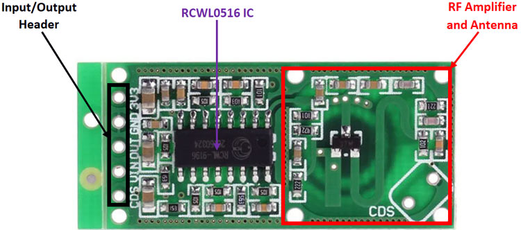
Internal Circuit Diagram for RCWL0516 Module
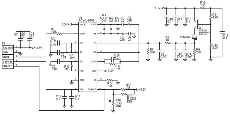
RCWL0516 IC, which is a complete RF Doppler system in a chip is the heart of the module. The peripheral components act as power supply decoupling and filtering and set operating points. The RF section consists of a high-speed NPN transistor Q1, which forms a Colpitts oscillator. The antenna is a trace on the PCB.
The transistor Q1 also acts as a mixer that combines the transmitted and received signal and outputs the difference which is filtered by the low pass filter formed by C9 and R8, and is amplified by the IC. This signal can be treated the same way as the signal from a PIR sensor.
How to use the RCWL0516 Module?
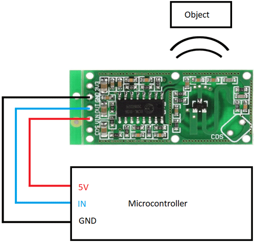
The output of the RCWL0516 sensor is analog and can be connected to an analog input of a microcontroller and sampled by an ADC. The output voltage is roughly proportional to the distance between the sensor and the object. However, since it relies on a Doppler radar system, signal reflections from other nearby objects can interfere with the measurement, making it less reliable and accurate than other kinds of sensors. The reflections from different kinds of objects can also influence measurements, for example, metallic objects have a stronger reflection than plastic objects.
RCWL0516 Module Basic Troubleshooting
- If the module does not output a signal:
- Check the power supply
- Check if the correct pin is connected to the microcontroller
- If the signal is intermittent or distorted:
- Check the clearance between the sensor and the object to be measured and other objects.
RCWL0516 Module Applications
- Distance sensing
- Radar applications
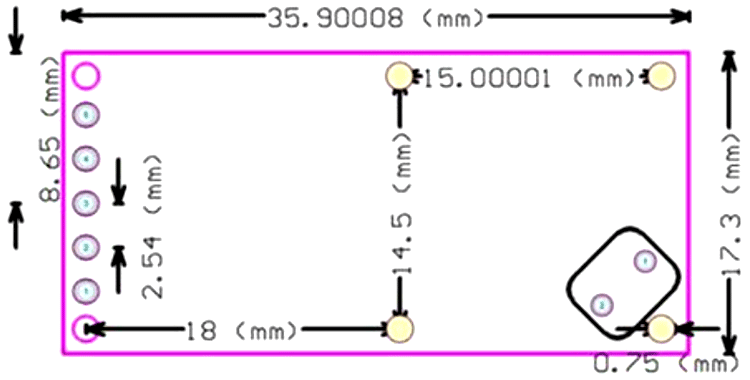
2D Model of The Module
The dimensions of RCWL0516 are given below to help you with selecting the right PCB footprint for RCWL0516.