Rain drop Sensor Module
Raindrop Sensor is a tool used for sensing rain. It consists of two modules, a rain board that detects the rain and a control module, which compares the analog value, and converts it to a digital value. The raindrop sensors can be used in the automobile sector to control the windshield wipers automatically, in the agriculture sector to sense rain and it is also used in home automation systems.
Pin Configuration of Rain Sensor:
|
S.No: |
Name |
Function |
|
1 |
VCC |
Connects supply voltage- 5V |
|
2 |
GND |
Connected to ground |
|
3 |
D0 |
Digital pin to get digital output |
|
4 |
A0 |
Analog pin to get analog output |
Raindrop Sensor Features:
- Working voltage 5V
- Output format: Digital switching output (0 and 1), and analog voltage output AO
- Potentiometer adjust the sensitivity
- Uses a wide voltage LM393 comparator
- Comparator output signal clean waveform is good, driving ability, over 15mA
- Anti-oxidation, anti-conductivity, with long use time
- With bolt holes for easy installation
- Small board PCB size: 3.2cm x 1.4cm
Note: The complete technical details can be found in the Rain Sensor datasheet given at the bottom of this page.
How to use Raindrop sensor:
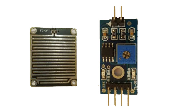
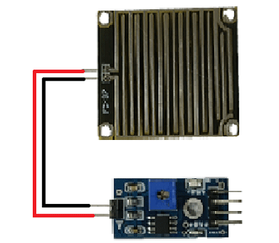
Interfacing the raindrop sensor with a microcontroller like 8051, Arduino, or PIC is simple. The rain board module is connected with the control module of the raindrop sensor as shown in the below diagram.
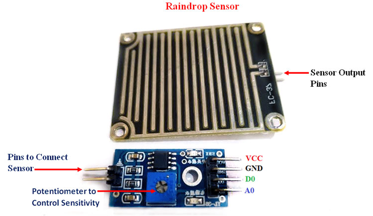
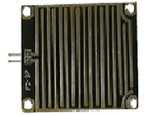
The control module of the raindrop sensor has 4 outputs. VCC is connected to a 5V supply. The GND pin of the module is connected to the ground. The D0 pin is connected to the digital pin of the microcontroller for digital output or the analog pin can be used. To use the analog output, the A0 pin can be connected to the ADC pin of a microcontroller. In the case of Arduino, it has 6 ADC pins, so we can use any of the 6 pins directly without using an ADC converter. The sensor module consists of a potentiometer, LN393 comparator, LEDs, capacitors and resistors. The pinout image above shows the components of the control module. The rainboard module consists of copper tracks, which act as a variable resistor. Its resistance varies with respect to the wetness on the rainboard. The below fig shows the rain board module.
The circuit diagram of a raindrop sensor module is given below.
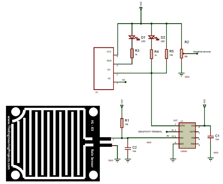
As shown in the above figure, the R1 resistor and the rain board module will act as a voltage divider. Capacitors C1 and C2 are used as a biasing element. The input for the Non-inverting terminal is taken from the connection point of the R1, and rain board module. Another point is taken from this connection and connected to the A0 terminal of the control module.
The input to the inverting terminal of the LM393 is taken from the potentiometer (R2). The R2 resistor acts as a voltage divider, and by varying R2 we can vary the input voltage to the inverting terminal, which in turn affects the sensitivity of the control module. The connections are shown in the above fig. The resistors R3 and R4 will act as current limiting resistors, while resistor R5 will act as a pull-up resistor to keep the bus in a high state when not in use.
Working of Rain Sensor:
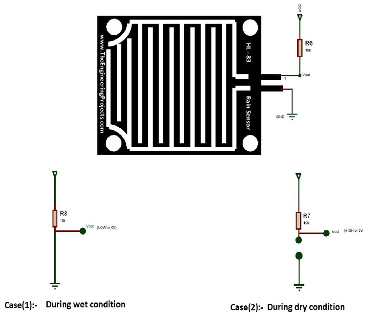
Case1: When the input of the inverting terminal is higher than the input of the non-inverting terminal.
Case2: If the input of the inverting terminal is lower than the input of the non-inverting terminal.
The input to the inverting terminal is set to a certain value by varying the potentiometer and the sensitivity is set. When the rain board module’s surface is exposed to rainwater, the surface of the rainboard module will be wet, and it offers minimum resistance to the supply voltage. Due to this, the minimum voltage will be appearing at the non-inverting terminal of LM393 Op-Amp. The comparator compares both inverting and non-inverting terminal voltages. If the condition falls under case(1), the output of the Op-Amp will be digital LOW. If the condition falls under case(2), the output of the Op-Amp will be digital HIGH. The below diagram shows the equivalent circuit of both the conditions.
When the A0 pin is connected to the microcontroller, an additional analog to digital converter (ADC) circuit is used. In the case of Arduino, it consists of 6 ADC pins, which can be directly used for calculation purposes.
Applications of Rain sensor:
- Automatic windshield wipers
- Smart Agriculture
- Home-Automation


