HC-SR505 PIR Motion Sensor Module
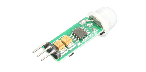
HC-SR505 is mini PIR (Passive Infra Red) motion sensor module, which as the name implies used for detecting the motion of a body in front of it. The device works based on infrared technology and it can automatic control by itself with high sensitivity and high reliability. Because of the minimum size and low-power operation mode, it widely used in battery-powered applications.
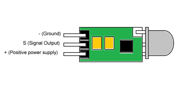
Pin configuration
HC-SR505 is a three pin device as shown in figure and the function of each pin is stated below.
|
Pin |
Name |
Function |
|
- |
Ground |
This pin is grounded for the operation of the module |
|
S |
Signal Output |
The module provides output signal at this pin |
|
+ |
Positive power supply |
A positive voltage of minimum +5V is supplied at this pin for the device |
HC-SR505 Features and Electrical characteristics
- Wide range of operating voltage
- Minimum size
- Repeatable trigger
- Low power consumption
- Automatic control
- Trigger: reusable trigger by default
- Sensing distance: 3 meters
- Sensor lens dimensions: diameter- 10mm
- Operating voltage range: +4.5V to +20V
- Maximum operating voltage: +20V
- Operating temperature range: -20ºC to 80ºC
- Quiescent current: <60µA
- Induction angle: <100 degrees cone angle
HC-SR505 Alternatives
HC-SR01
HC-SR505 Overview
The module is basically used in applications where you want to detect the motion of a body which emits infrared radiations. HC-SR505 is preferred to be used in battery operated systems since the device is specifically designed to be operated by consuming very less power. Because of its small size the module can be installed in applications where the system size is taken in to consideration.
How to use HC-SR505 Sensor
The device HC-SR505 can be installed in any system easily all you need to do is, connect the power to the module and receive the response from it. Let us consider simple application circuit of the device as an example.
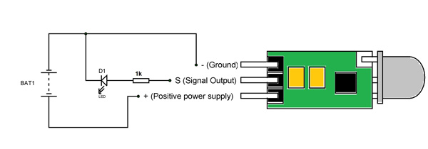
In circuit
- The device is powered from a DC power source and it can range from +5V to +20V and in the circuit we are using +5V power source.
- The device response or output is connected to a LED to visualize the device response.
- The 1KΩ resistor is for limiting the current output from the device.
Working: For instance consider the module is powered and the lens of device is facing a solid wall. Under such case the sensor does not detect any IR (Infra Red) radiation change from the wall and it will provide LOW at the output pin. So when the device is faced solid walls and unmoving things the output will be LOW and the LED will be OFF.
Now if a human or a dog passes through its detecting area opposite to its lens, the module will detect the change in the IR radiation (as the living body emits IR radiation) and as a response provides HIGH logic at the output pin. So when the device detects a living body or IR emitting things the output will be HIGH and the LED will get turned ON.
This way we can use the device to detect motion of living things in front of its lens. We can connect the signal output to any microcontroller or arduino to do many fun things.
Applications
- Motion alarm
- Automatic lighting system
- Theft protection
- Staircase lighting system
- Hobby projects
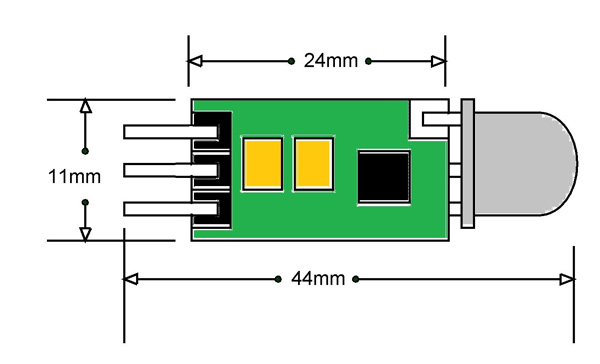
2D-Model