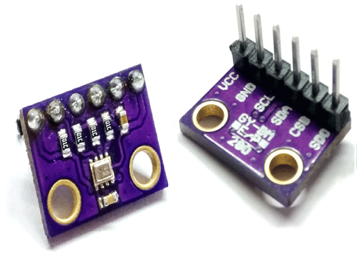
GY-BMP280 Module
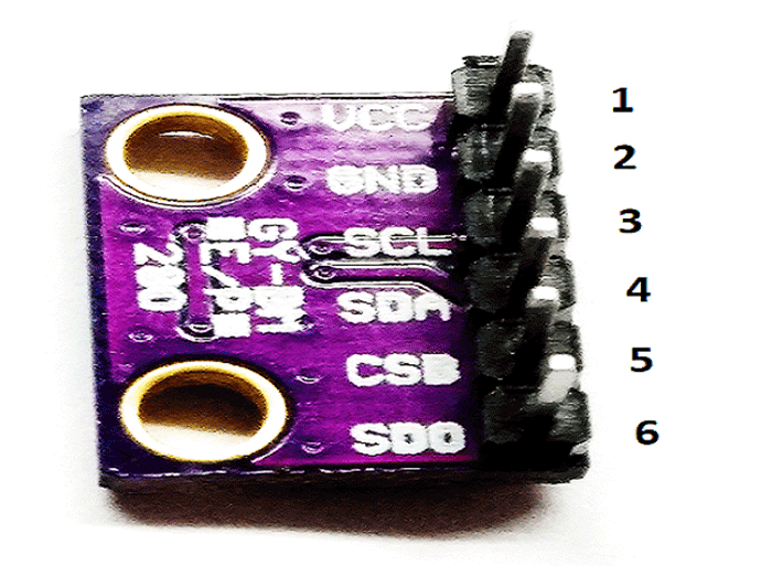
GY-BMP280 Pin configuration
|
Pin No. |
Pin Name |
Pin Description |
|
1 |
VCC |
Power source of 3.3VDC |
|
2 |
GND |
Ground |
|
3 |
SCL |
Serial Clock |
|
4 |
SDA |
Serial Data |
|
5 |
CSB |
CSB pin to GND to have SPI and to VCC(3.3V) for I2C. It’s an input to the chip. |
|
6 |
SDO |
Serial Data Out / Master In Slave Out pin, for data sent from the BMP280 to your processor |
Features
- The GY-BMP280 module comes with BMP280 sensor, which is an environmental sensor with temperature, barometric pressure that is the next generation upgrade to the BMP085/BMP180/BMP183.
- This sensor is great for all sorts of weather sensing and can even be used in both I2C and SPI.
- This precision sensor is the best low-cost, precision sensing solution for measuring barometric pressure with ±1 hPa absolute accuracy, and temperature with ±1.0°C accuracy. Because pressure changes with altitude and the pressure measurements are so good, you can also use it as an altimeter with ±1 meter accuracy
- Pin pitch: 2.54mm
- Module size: 11.5mm*15mm
Electrical Specifications of GY-BMP280 Module
- Model: GY-BMP280-3.3
- Chip: BMP280
- Power supply: 3V/3.3V DC
- Peak current: 1.12mA
- Air pressure range : 300-1100hPa (equi. to +9000…-500m above sea level)
- Temperature range: -40 … +85 °C
- Digital interfaces: I²C (up to 3.4 MHz) and SPI (3 and 4 wire, up to 10 MHz)
- Current consumption of sensor BMP280: 2.7µA @ 1 Hz sampling rate
Brief about GY-BMP280 Module
The GY-BMP280 Barometer Sensor is a breakout board for Bosch BMP280 high-precision and low-power digital barometer. It can be used to measure temperature and atmospheric pressure accurately. It can be connected to a microcontroller with I2C.
How to use GY-BMP280 Module?
The GY-BMP280 module operates from 3.3V so requires 3.3V power and must be driven with 3.3V logic levels. If needed to operate at 5V, it can be done using voltage regulator and level shifters as it doesn’t contain one. It is typically recommended to operate it on 3.3V and maximum at 3.6VDC. The module GY-BMP280 module simply supports both I²C and SPI interfaces and comes with default I²C address of 0x76. The Chip Select (CSB) and Serial Data Output (SDO) pins of the BMP280 are necessary only when SPI-based (four-wire) communication is applied. I2C is a two wire interface SDA SCK.
Leave pin 6 of the module (SDO) unconnected to set the I²C address to 0x76 – the on-board resistor pulls the SDO pin low setting the address to 0x76.
To change the I²C address to 0x77, connect pin 6 of the module (SDO) to Vcc which would typically be the 3.3V supply.
Pin 5 of the module (CSB) must be connected to Vcc to select the I²C interface. This is already done by an on-board pull-up resistor, so pin 5 can be left disconnected when using the I²C interface.
Applications of GY-BMP280 Module
- Enhancement of GPS navigation (e.g. time-to-first-fix improvement, dead-reckoning, slope detection)
- Indoor navigation (floor detection, elevator detection)
- Outdoor navigation, leisure and sports applications
- Weather forecast, Home weather stations
- Health care application (e.g. sirometry)
- Vertical velocity indication (e.g. risk/sink speed)
- Handsets such as mobile phones, tablet PCs, GPS devices
- Flying toys
- Watches


