IRF640N N-Channel Power MOSFET Pinout, Equivalents & Datasheet Guide
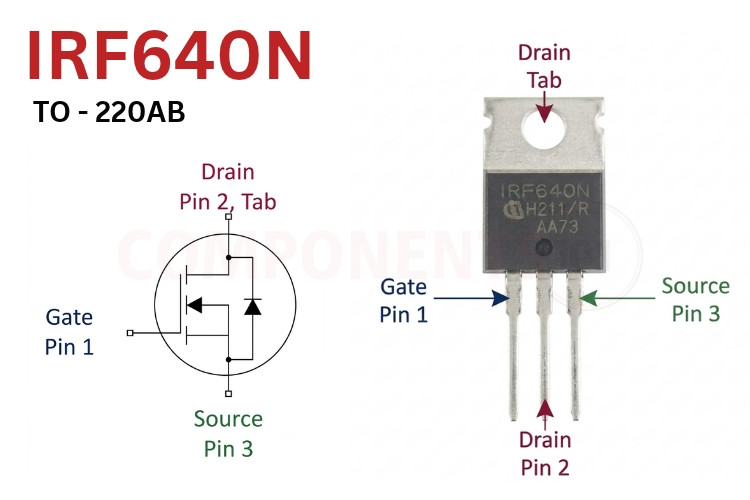
IRF640N Pinout Configuration
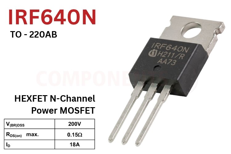
When holding the IRF640N in its through-hole `TO-220AB` package with the front markings facing you and the leads pointing downward, the terminals follow the standard GDS MOSFET pin assignment from left to right.
This page covers the IRF640N pinout, key datasheet values, IRF640N equivalents, the IRF640 vs IRF640N difference and package dimensions.
| Pin Number | Pin Name | Description |
| 1 | Gate (G) | Controls MOSFET turn-on and turn-off; requires 10V VGS for full 0.15 Ω saturation |
| 2 | Drain (D) | High-voltage current input terminal from the load (internally connected to metal tab) |
| 3 | Source (S) | Current return terminal connected to circuit ground in low-side switching configurations |
| Metal Tab | Drain (D) | Internally tied to Pin 2; use an insulating pad and bushing if bolting to a grounded heatsink |
IRF640N Package Variants & Ordering Information
Infineon (formerly International Rectifier) manufactures the IRF640N silicon die across three RoHS-compliant lead-free (`PbF`) packages to support through-hole heatsink mounting and high-density SMD PCB assembly.
| Orderable Part Number | Package | Mounting Style | Standard Packing |
| IRF640NPbF | TO-220AB | Through-Hole (3-Pin + Tab) | Tube (50 units) |
| IRF640NSPbF | D²Pak (TO-263AB) | Surface-Mount (SMD) | Tape & Reel (800 units) |
| IRF640NLPbF | TO-262 (I²Pak) | Through-Hole (Straight Leads) | Tube (50 units) |
IRF640N MOSFET Features and Specifications
- Polarity & Technology: N-Channel Enhancement-Mode HEXFET Power MOSFET
- Drain-to-Source Breakdown Voltage (V(BR)DSS): 200V (`VGS = 0V`, `ID = 250 µA`)
- Static On-Resistance (RDS(on)): 0.15 Ω (150 mΩ) max at `VGS = 10V`, `ID = 11A`
- Continuous Drain Current (ID): 18A at `TC = 25°C`; 13A at `TC = 100°C` (`VGS = 10V`)
- Pulsed Drain Current (IDM): 72A (pulse width limited by maximum junction temperature)
- Gate Threshold Voltage (VGS(th)): 2.0V min to 4.0V max (`VDS = VGS`, `ID = 250 µA`) - Standard gate drive
- Maximum Gate-to-Source Voltage (VGS): ±20V
- Total Gate Charge (Qg): 67 nC max (`Qgs = 11 nC` max, `Qgd = 33 nC` max at `VDS = 160V`, `ID = 11A`)
- Switching Speed (`VDD = 100V`, `ID = 11A`, `RG = 2.5 Ω`): `td(on) = 10 ns`, `tr = 19 ns`, `td(off) = 23 ns`, `tf = 5.5 ns`
*Note: Complete Technical Details can be found in the IRF640N datasheet given at the end of this page.
IRF640N Equivalent and Alternative MOSFETs
If you need a complementary P-channel device for push-pull output stages, a lower-resistance upgrade, or a drop-in second-source replacement for the IRF640N, consider these parts. Use the table below to find an IRF640N equivalent for repair, a second source for production, a P-channel complement for push-pull stages, or an upgrade with lower conduction loss. The most common IRF640N circuit is a low-side switch: the load sits between the positive supply and the Drain, the Source goes to ground, and a 10V–12V signal on the Gate turns the load on.
| Part Number | Key Ratings (VDS / ID / RDS(on)) | Remarks & Comparison |
| IRF9640 | -200V, -11A, 0.50 Ω (TO-220AB) | Complementary P-Channel counterpart for push-pull audio amplifiers and high-side switches |
| IRF640 | 200V, 18A, 0.18 Ω (TO-220AB) | Legacy predecessor with higher on-resistance (180 mΩ vs. 150 mΩ) and higher gate charge |
| IRF630 | 200V, 9A, 0.35 Ω (TO-220AB) | Lower-current sibling suited for medium-power 200V switching under 9A |
| IRF740 | 400V, 10A, 0.55 Ω (TO-220AB) | Higher-voltage (400V) alternative for off-line SMPS stages where load current is below 10A |
| IRFP250N | 200V, 30A, 0.075 Ω (TO-247AC) | Higher-current upgrade in a larger TO-247 package with half the conduction loss |
| STP19NF20 / FQP19N20 | 200V, 18–19A, ~0.14 Ω (TO-220) | Pin-compatible second-source N-channel alternatives for 200V inverters and converters |
Brief Description of IRF640N
Standard 10V Gate Drive Requirement (Not 3.3V Logic-Level): Although conduction starts between 2.0V and 4.0V, the IRF640N requires `VGS = 10V` to reach its full 0.15 Ω saturation channel. Driving the gate directly from a 3.3V or 5V microcontroller GPIO restricts drain current and triggers severe resistive heating; always insert a 10V–12V gate driver IC or optocoupler/transistor level-shifter.
200V Margin for 48V–120V Bus Rails: Switching inductive coils, transformers, or DC motors creates voltage flyback spikes during turn-off. The `200V` breakdown rating gives a wide safety margin over nominal 48V, 72V, 96V, and 110V DC rails without forcing designs into high-RDS(on) 400V–600V MOSFETs. Many searches for the IRF640 datasheet and IRF640 MOSFET are actually looking for the IRF640N, or wondering whether the two are interchangeable.
IRF640N Datasheet
Download the full IRF640N datasheet below for characteristic curves, safe operating area (SOA), avalanche ratings and test circuits.
Applications
- High-voltage DC-DC boost, flyback, and forward converters (48V–150V rails)
- Uninterruptible Power Supplies (UPS) and DC-AC off-grid power inverters
- High-power Class-AB and Class-D audio amplifier output stages (paired with IRF9640)
- Brushed DC motor controllers, e-bike drives, and industrial solenoid actuators
- Solar MPPT charge controllers and battery disconnect / solid-state relay switches
IRF640N TO-220AB Package Dimensions
All physical dimensions below correspond to the Infineon PG-TO220-3-U05 (TO-220AB) package outline shown in the drawing and are specified in millimetres (`mm`) unless noted otherwise.
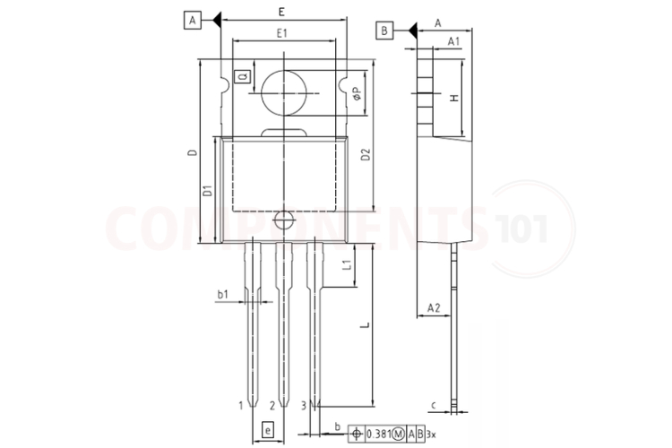
| Symbol | Dimension Description | Minimum (mm) | Maximum (mm) |
| A | Overall Package Thickness | 3.56 | 4.83 |
| A1 | Heatsink Tab Thickness | 1.14 | 1.40 |
| A2 | Seating Plane to Back of Body | 2.03 | 2.92 |
| b | Lead Tip Width | 0.38 | 1.01 |
| b1 | Upper Lead Shoulder Width | 1.14 | 1.78 |
| c | Lead Thickness | 0.36 | 0.61 |
| D | Overall Body + Tab Height | 14.22 | 16.51 |
| D1 | Plastic Mold Body Length | 8.38 | 9.20 |
| E | Package Width | 9.65 | 10.67 |
| e | Pin-to-Pin Center Pitch | 2.54 (Typ) | - |
| H | Exposed Metal Tab Height | 5.84 | 6.86 |
| L | Lead Length below Body | 12.70 | 14.73 |
| L1 | Lead Shoulder Length | 3.56 | 4.06 |
| øP | Mounting Hole Diameter | 3.54 | 4.08 |
| Q | Mounting Hole Center to Tab Top | 2.54 | 3.42 |