
Redefining Connectivity: AIROC™ CYW55913 modules for IoT, Smart Home, Industrial
Slew Rate vs Skew in Electronics: Definitions, Differences, and Common Misconceptions
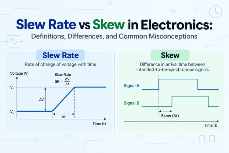
When designing or troubleshooting high-speed electronics, you will frequently hear two terms thrown around during lab testing, Slew Rate and Skew. Because they sound remarkably similar and both describe timing performance, beginners and even experienced hardware engineers frequently mix them up. However, beneath the similar names lie two entirely different physical principles:
Slew Rate describes how fast a single voltage signal can change over time. Skew describes the timing mismatch between two or more signals traveling across a circuit.
In this article, we break down what each term really means, bust the common "skew rate" terminology myth, explore where each parameter matters on the workbench, and look at the hidden link where slew rate actually creates timing skew.
The “Skew Rate” Reality Check
Before diving into circuit behavior, it is important to clarify a common terminology misconception. In standard engineering terminology, “skew rate” is not generally recognised as a formal parameter in standards such as IEEE, JEDEC, or IPC. The two established terms are slew rate and skew, which describe fundamentally different aspects of a signal.
| Term | Meaning | Units | What it describes |
| Slew Rate | Rate of voltage change | V/µs or V/ns | How quickly or steeply a signal transitions from one voltage level to another |
| Skew | Difference in signal arrival times | ps or ns | How far apart two signals arrive at their respective destinations |
Slew is a rate, expressed as voltage divided by time, and it describes the steepness of a signal’s rising or falling edge. Skew, on the other hand, is a time difference, expressed in picoseconds or nanoseconds, and indicates how much earlier or later one signal arrives compared with another. The term “skew rate” is therefore best avoided in formal technical communication unless it is explicitly defined for a particular context. In informal discussions, the phrase may sometimes be used to describe how skew changes with PCB trace length, such as ps/inch, but this is more appropriately described as skew per unit length or propagation-delay difference per unit length.
To keep it clear: slew tells you how steeply a signal changes voltage, while skew tells you how far apart two signals are in time when they arrive at their destinations.
What is Slew Rate?
Think of slew rate as the acceleration pedal of an electronic amplifier or output driver. In a real-world circuit, the output voltage cannot change instantaneously; for example, a transition from 0 V to 5 V cannot occur in zero time. The rate of this voltage transition is limited by factors such as internal capacitances, available drive current, and the characteristics of the output transistors.
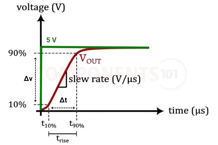
The Slew Rate (SR) specifies the maximum rate at which a device can change its output voltage over time. It can be expressed as:
SR = ΔV / Δt
where ΔV represents the change in output voltage (in volts), and Δt represents the time required for that voltage transition. A higher slew rate means that the device can produce a faster voltage transition, resulting in a steeper rising or falling edge. The unit used depends on the application. V/µs is commonly used for operational amplifiers and audio drivers, while V/ns is more appropriate for high-speed digital logic and power MOSFET gate drivers. In simple terms, slew rate tells us how quickly a circuit can move its output voltage from one level to another.
Where Slew Rate Matters Most
Operational Amplifiers and Audio Circuits:
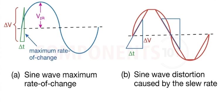
If an incoming sine wave demands an output voltage change faster than the op-amp's rated slew rate, the amplifier cannot keep up. Instead of a smooth sine wave, the output turns into a distorted triangular wave. This creates harsh acoustic distortion (slew-induced distortion, or SID) in audio gear.
Power MOSFET and IGBT Gate Drivers:
In motor drivers, inverters, and switch-mode power supplies (SMPS), the speed at which the gate voltage switches on and off determines how fast the transistor transitions through its high-dissipation linear region.
| Condition | Consequences |
| Too Slow | The MOSFET spends too much time partially turned on, dissipating power as heat and potentially burning out. |
| Too Fast | Rapid switching generates massive electromagnetic interference (EMI), voltage spikes across parasitic trace inductances, and destructive ringing. |
Microcontroller GPIO Output Pins:
Modern microcontrollers (such as STM32, ESP32, and RP2040) allow firmware to configure output pin slew rates (often labelled Low, Medium, or High drive speed). Using the lowest slew rate that still meets your communication baud rate prevents radiated radio frequency emissions and stops high-frequency ringing on breadboard wires.
What is Skew? (The Timing Gap Between Multiple Signals)
If slew rate is about a single runner’s acceleration, skew is about two runners who were supposed to arrive at the finish line at the same instant, but did not.
In electronics, skew refers to the difference in arrival time between two or more signals that are intended to be synchronized or reach their destinations simultaneously. It is therefore a time difference, rather than a rate of voltage change. The skew between two signals can be expressed as,
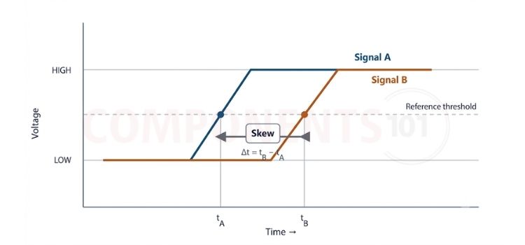
t_skew = |t_arrival,Signal A − t_arrival,Signal B| where t_arrival, Signal A is the time at which Signal A crosses a defined reference threshold, and t_arrival, Signal B is the time at which Signal B crosses the same reference threshold. The absolute value ensures that skew is expressed as a positive time difference. Skew is commonly measured in picoseconds (ps) or nanoseconds (ns). For example, if Signal A reaches the reference threshold at 10.000 ns and Signal B reaches it at 10.080 ns, the resulting skew is 80 ps. In simple terms, slew rate tells us how quickly a signal changes voltage, while skew tells us how far apart two signals are in time when they arrive at their destination.
Where Skew Matters Most
Clock Distribution in Digital Systems (Clock Skew):
In synchronous digital systems (such as microprocessors, FPGAs, and digital signal processors), a master clock signal must trigger thousands of flip-flops simultaneously. If the clock arrives at Flip-Flop B slightly later than Flip-Flop A (due to unequal PCB trace lengths or buffer delays), the system can suffer from setup time or hold time violations, causing data corruption or complete processor crashes.
Differential Communication Pairs (Intra-Pair Skew):
High-speed protocols like USB, HDMI, Ethernet, and CAN bus transmit data over a pair of complementary differential wires (such as D+ and D-, or CAN_H and CAN_L). If one trace is slightly longer than the other, or routes over a different dielectric constant in the PCB fibreglass, the two complementary signals become phase-shifted.
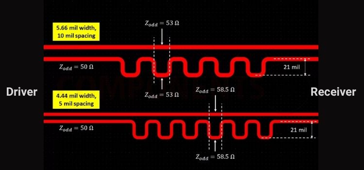
This intra-pair skew turns clean differential signals into common-mode electromagnetic noise, failing regulatory EMC testing and degrading the receiver's eye diagram.
Parallel Memory and Data Buses (Inter-Signal Skew):
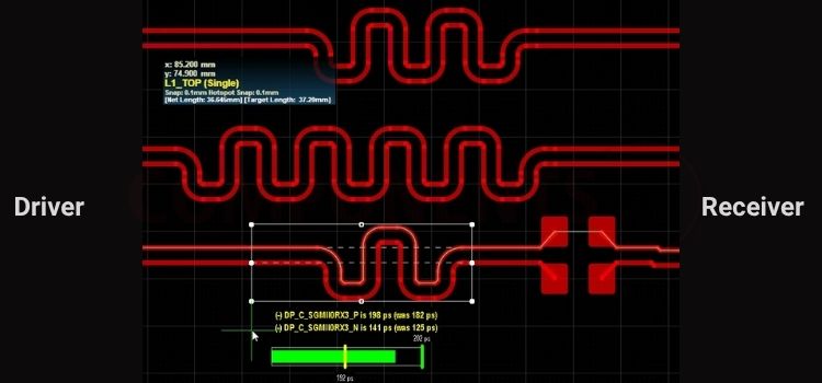
In parallel interfaces like DDR RAM or camera sensor interfaces, eight or sixteen data bits must arrive alongside a strobe or clock line. If bit 0 arrives 500ps ahead of bit 7, the memory controller samples invalid data words.
Head-to-Head Comparison: Slew Rate vs Skew
To clearly separate these two concepts in your bench work, refer to this quick reference matrix:
| Feature | Slew Rate (SR) | Signal / Clock Skew (t_skew) |
| What does it measure? | The slope or edge speed of a single voltage transition | The arrival time mismatch between two or more signals |
| Physical Dimension | Voltage / Time (ΔV / Δt) | The arrival time mismatch between two or more signals |
| Standard Units | V/µs (analog/op-amps) or V/ns (digital/gate drivers) | ps or ns |
| Primary Domain | Analog amplifiers, audio, power switching, I/O buffers | Synchronous digital logic, clock trees, differential pairs |
| Typical Root Cause | Internal compensation capacitor, tail current, driver strength | Mismatched PCB trace lengths, component propagation delays |
| Failure Symptom | Waveform distortion (sine becomes triangle), excess switching heat | Timing violations, data corruption, common-mode EMI noise |
| Bench Measurement | Measure edge voltage rise between 10% and 90% points on an oscilloscope | Measure horizontal time delta between two channel threshold crossings |
| How to Fix / Tune | Choose a faster op-amp, or tune the gate series resistor (Rg) | Add serpentine meanders to equalize PCB trace lengths, balance clock trees |
The Hidden Connection: How Slew Rate Directly Creates Skew
Although slew rate and skew are distinct parameters, they are not completely independent. In high-speed hardware, differences in slew rate can translate into differences in the time at which signals cross a receiver’s detection threshold, thereby creating timing skew even when the physical trace lengths are identical.
Consider two digital output drivers connected to two parallel PCB traces of the same physical length:
| Driver A | Fast Slew Rate: 2.0 V/ns | Receiver A |
| Driver B | Slow Slew Rate: 1.0 V/ns | Receiver B |
Even though both traces have identical lengths, the receiver does not necessarily recognize a signal as HIGH the moment its voltage begins to rise. Instead, the receiver detects the transition when the signal crosses a specified logic threshold. For this simplified example, assume the threshold is 1.65 V, which is 50% of a 3.3 V supply. Assuming both signals start from 0 V and rise linearly, the time required for each signal to reach the threshold is:
For Driver A: t_A = 1.65 V / 2.0 V/ns = 0.825 ns For Driver B: t_B = 1.65 V / 1.0 V/ns = 1.650 ns
Therefore, the difference in threshold-crossing time is:
t_skew = t_B − t_A = 1.650 ns − 0.825 ns = 0.825 ns = 825 ps
The important point is that 825 ps of timing difference has been created solely by the difference in slew rates, even though there is no PCB trace-length mismatch in this simplified example. This illustrates the hidden relationship between slew rate and skew: skew is ultimately determined by when signals cross the relevant timing threshold, and slew rate influences how quickly that crossing occurs. For this reason, high-speed PCB design cannot rely on trace-length matching alone. Designers also need to consider factors such as capacitive loading, output-driver characteristics, trace impedance, and signal return paths, because differences in these parameters can alter the shape and timing of signal edges and consequently contribute to timing uncertainty or skew.
Conclusion
Slew rate and skew are distinct but closely related concepts in high-speed circuit design. Slew rate determines how quickly a signal transitions, while skew describes the timing difference between signals. Understanding both is essential for reliable signal integrity and timing performance. In the next articles, we’ll explore these concepts in greater depth.
- Understanding Slew Rate in Op-Amps and How to Measure and Calculate it for your Designs
- Understanding Skew in Digital Systems: Clock timing, setup/hold margins, PCB length matching, and differential-pair skew.