CAN Transceiver ICs and Physical Layer Guide: TJA1050, SN65HVD230, MCP2551, TJA1051, and CAN FD
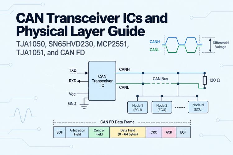
A CAN Transceiver is a dedicated physical-layer interface IC that serves as the bridge between a digital CAN controller (such as the MCP2515 or the built-in CAN/TWAI peripherals inside ESP32 and STM32) and the physical differential wiring of the Controller Area Network (CAN) bus. Operating at OSI Layer 1 (Physical Layer - ISO 11898-2), the CAN transceiver performs two essential functions.
Transmitting: Converts single-ended digital logic signals (TXD) from the microcontroller into high-voltage differential signal pairs (CANH and CANL) driven onto the twisted-pair cable.
Receiving: Senses the differential voltage across CANH and CANL, suppresses common-mode electromagnetic noise and ground shifts, and translates the bus state back into clean digital logic levels (RXD) for the host controller.
This guide covers CAN physical layer fundamentals, differential bus voltage levels, a working CAN Transceiver Circuit, the TJA1050 Pinout and datasheet specifications, 3.3V vs. 5V transceiver interoperability, CAN BUS Termination Resistor, split termination networks, the MCP2551 CAN Transceiver and an in-depth comparison of industry-standard transceivers (TJA1050, SN65HVD230, MCP2551, TJA1051, and TCAN1042).
CAN Physical Layer Fundamentals: Differential Signalling & Bus States
The CAN bus achieves its electromagnetic noise immunity and multi-node arbitration capability through differential signalling. The physical state of the bus is defined by the voltage difference (Vdiff = VCANH - VCANL) rather than the absolute voltage with respect to ground.
The Two Physical Bus States:
| Parameter | Recessive State (Logic 1) | Dominant State (Logic 0) |
| Logic Level | Digital HIGH (Logic 1) | Digital LOW (Logic 0) |
| TXD Input | Driven HIGH or left floating (Internal pull-up) | Driven LOW by microcontroller |
| Transceiver Output | High-Impedance / Passive (Transmitters OFF) | Actively Driven (Transmitters ON) |
| VCANH Voltage | ≈ 2.5 V (Nominal for 5V transceivers) | ≈ 3.5 V (2.75 V to 4.5 V) |
| VCANL Voltage | ≈ 2.5 V (Nominal for 5V transceivers) | ≈ 1.5 V (0.5 V to 2.25 V) |
| Vdiff | Vdiff ≈ 0.0 V (-0.5 V to +0.5 V) | Vdiff ≈ 2.0 V (+1.5 V to +3.0 V) |
| Receiver Interpretation | Vdiff < 0.5 V = Logic 1 (RXD = HIGH) | Vdiff > 0.9 V = Logic 0 (RXD = LOW) |
Why Dominant Overwrites Recessive:
Because the Recessive state is high-impedance (passively held at approximately 2.5 V via internal biasing resistors), any node that actively drives the bus into the Dominant state will pull CANH up to approximately 3.5 V and CANL down to approximately 1.5 V.
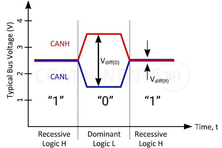
This creates a wired-AND logic behaviour: if multiple nodes transmit simultaneously, a Dominant bit (Logic 0) always overwrites a Recessive bit (Logic 1) without causing short circuits or bus contention. This fundamental mechanism enables non-destructive bitwise arbitration (CSMA/CD + AMP) and automatic hardware acknowledgement (ACK) bits.
Standard 8-Pin CAN Transceiver Pinout
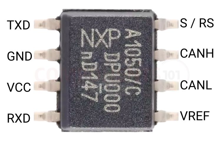
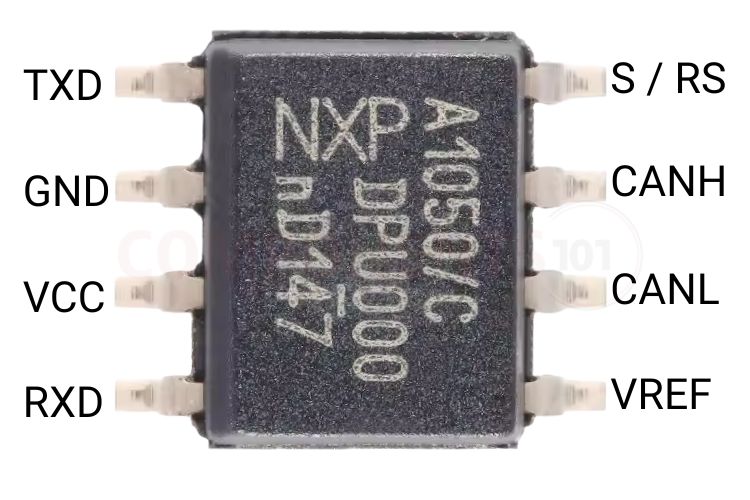
Most industry-standard high-speed CAN transceivers follow the common 8-pin DIP / SOIC-8 pinout footprint (originally established by the Philips PCA82C250 and NXP TJA1050), allowing pin-for-pin PCB compatibility across multiple silicon vendors.
Pin Configuration Table
| Pin No. | Pin Name | Pin Type | Functional Description across Popular Transceivers |
| 1 | TXD | Input | Transmit Data Input: Driven by the host CAN controller. Driving TXD LOW forces the bus into the Dominant state; driving TXD HIGH releases the bus to the Recessive state. Contains an internal pull-up. |
| 2 | GND | Power | Ground reference (0 V). |
| 3 | VCC | Power | Transceiver Supply Voltage: 5.0 V DC for TJA1050, TJA1051, and MCP2551; 3.3 V DC for SN65HVD230 / SN65HVD232. |
| 4 | RXD | Output | Receive Data Output: Reflects the physical bus state. Outputs digital LOW when the bus is Dominant and digital HIGH when the bus is Recessive. |
| 5 | VREF / NC / VIO | Power / Aux | Variant-Specific Function: • TJA1050: Reference voltage output • MCP2551: VREF output (approximately 0.5 × VCC reference voltage for split termination). • TJA1051T/3 & TCAN1042V: VIO input (supply voltage for the digital logic interface, allowing direct 3.3 V MCU connection). • SN65HVD230: VREF output (approximately 2.3 V reference). |
| 6 | CANL | I/O | CAN Low Differential Bus Line. |
| 7 | CANH | I/O | CAN High Differential Bus Line. |
| 8 | S / Rs | Input | Operating Mode & Slope Control Pin: • TJA1050 (S): Connect to GND for High-Speed Mode; pull HIGH to VCC for Silent/Listen-Only Mode. • MCP2551 (Rs): Connect to GND for High-Speed Mode; connect through a 10 kΩ-100 kΩ resistor to GND for Slope Control Mode; pull HIGH for Standby. • SN65HVD230 (Rs): Connect to GND for High-Speed Mode; connect through a 10 kΩ-100 kΩ resistor for Slope Control; pull HIGH for Ultra-Low-Power Standby (approximately 370 µA). |
3.3V vs. 5V Transceivers & Bus Interoperability
One of the most common questions among embedded engineers is: Can a 3.3V CAN transceiver (like the SN65HVD230) communicate on the same bus with a 5V CAN transceiver (like the TJA1050 or MCP2551)?
Physical Bus Level Compatibility
- Both 3.3 V and 5 V transceivers strictly adhere to the ISO 11898-2 physical layer standard.
- The CAN receiver on any transceiver evaluates the difference between CANH and CANL, not the absolute voltage to ground.
- Because both 3.3 V and 5 V transceivers produce a differential voltage (Vdiff) of approximately 2.0 V in the Dominant state and approximately 0.0 V in the Recessive state, 3.3 V and 5 V transceivers can seamlessly share the same physical twisted-pair bus.
Microcontroller Logic Level Compatibility
While the bus side is compatible, the microcontroller interface side requires careful attention:
- 5 V Transceivers (TJA1050, MCP2551): Their RXD output pin swings from 0 V to 5 V. Connecting this directly to a 3.3 V microcontroller (e.g., ESP32, STM32, RP2040) may overvoltage the GPIO pins. A voltage divider or level shifter is required unless the MCU input is specifically rated as 5 V tolerant.
- 3.3 V Transceivers (TI SN65HVD230 / SN65HVD232): Powered directly by 3.3 V, both TXD and RXD operate at 3.3 V logic levels, making them directly compatible with modern 3.3 V MCUs.
- Dual-Rail 5 V Transceivers with VIO Pin (NXP TJA1051T/3, TI TCAN1042V): Powered by 5 V on VCC, providing full 5 V bus drive capability, while VIO is connected to the MCU's 3.3 V rail. The RXD output then operates at the MCU's 3.3 V logic level.
A minimal CAN transceiver circuit for an MCU-based node needs just four connections
CAN BUS Termination Resistor: Standard vs. Split Termination
High-speed CAN networks require transmission-line impedance matching to prevent signal reflections, ringing, and frame corruption at high bitrates (up to 1 Mbps).
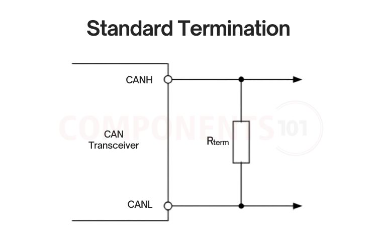
Standard Termination:
Consists of a single 120 Ω (1/4 W, 1% tolerance) metal-film resistor CAN BUS termination resistor placed between CANH and CANL at the two extreme physical ends of the bus, resulting in an effective parallel DC resistance of 60 Ω.
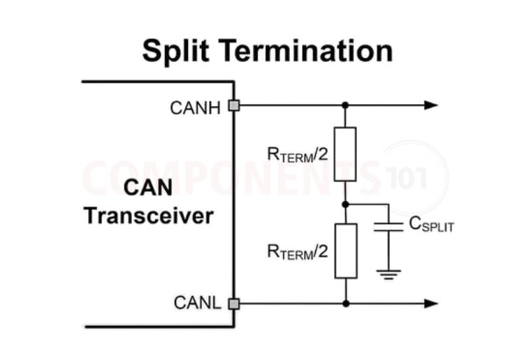
Split Termination:
The 120 Ω resistor can be divided into two series-connected 60 Ω precision resistors, with available values ranging from 59.0 Ω to 61.9 Ω at 1% tolerance. The center tap between the two resistors is connected to system ground through a 4.7 nF to 100 nF ceramic capacitor. This configuration forms a high-frequency RC low-pass filter that suppresses common-mode noise, significantly reducing electromagnetic emissions (EME) and helping stabilise the recessive common-mode voltage around VCC/2 (2.5 V), while avoiding any additional DC power dissipation.
The Microchip MCP2551 CAN transceiver is a widely used 5 V, high-speed part popular in legacy industrial CAN nodes and Arduino-based CAN projects paired with the MCP2515 controller
Comprehensive CAN Transceiver Comparison Matrix
The following table compares the most popular standalone CAN transceivers across electrical ratings, logic interface compatibility, power modes, and automotive certifications:
| Parameter | NXP TJA1050 | NXP TJA1051T/3 | TI SN65HVD230 | Microchip MCP2551 | TI TCAN1042-Q1 (CAN FD) |
| Supply Voltage (VCC) | 5.0 V DC | 5.0 V DC | 3.3 V DC | 5.0 V DC | 5.0 V DC |
| Logic Supply (VIO) | No (5 V Logic) | Yes (3.3 V / 5 V via Pin 5) | Native 3.3 V Logic | No (5 V Logic) | Yes (VIO on V-suffix) |
| Max. CAN Speed | 1 Mbps (CAN 2.0B) | Up to 5 Mbps (CAN FD) | 1 Mbps (CAN 2.0B) | 1 Mbps (CAN 2.0B) | Up to 5 Mbps (CAN FD) |
| Standby / Silent Mode | Silent Mode (Pin 8) |
Silent Mode (Pin 8) |
Ultra-Low Power Standby (370 µA) | Standby Mode (Pin 8) | Standby Mode with remote wake |
| Slope Control Feature | No (Fixed Slew Rate) | No | Yes (10 kΩ–100 kΩ) | Yes (10 kΩ–100 kΩ) | No (Optimised internally) |
| Bus Fault Protection | -27 V to +40 V | -58 V to +58 V | -12 V to +12 V | -42 V to +42 V | -70 V to +70 V |
| ESD Protection | ±4 kV | ±8 kV (IEC 61000-4-2) | ±16 kV (HBM) | ±6 kV (HBM) | ±16 kV (IEC Contact) |
| Common-Mode Range | -12 V to +12 V | -12 V to +12 V | -7 V to +12 V | -12 V to +12 V | -30 V to +30 V |
| Package | 8-Pin SOIC, DIP-8 | 8-Pin SOIC, HVSON-8 | 8-Pin SOIC, DIP-8 | 8-Pin SOIC, DIP-8 | 8-Pin SOIC, VSON-8 |
| Primary Use Case | Classic 5 V Arduino & Automotive | Modern 3.3 V/5 V Dual-Rail CAN FD | 3.3 V Systems (ESP32, STM32, Pico) | Legacy Industrial 5 V CAN Nodes | Next-Gen Rugged 24 V Automotive |
Typical Applications
- Automotive In-Vehicle Networks: Powertrain, body control modules, gateway ECUs, and OBD-II diagnostics.
- Industrial Automation & PLC Fieldbuses: CANopen, DeviceNet, and robust machine-to-machine sensor interfaces.
- Robotics & UAV Avionics: High-speed, noise-immune telemetry between flight controllers, ESC motor drivers, and IMU sensors.
- Battery Management Systems (BMS): High-voltage isolation and pack monitoring telemetry for electric vehicles and solar storage systems.