DAC7715 Digital to Analog Converter IC
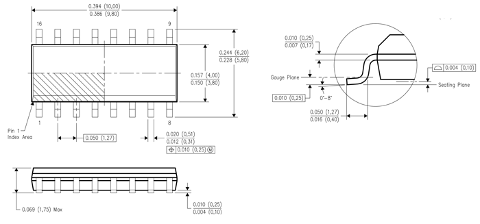
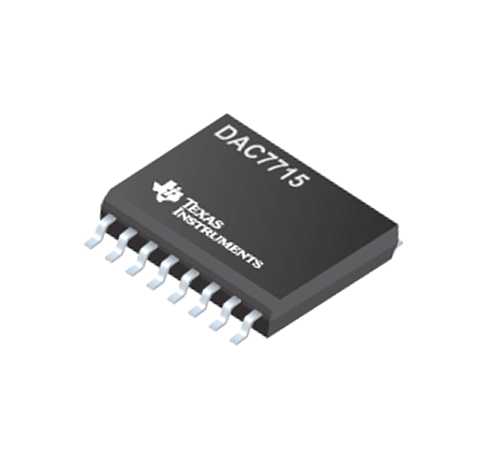
DAC7715 is a ‘Digital to Analog Converter’ chip designed by Texas Instruments and is available in SOIC-16 package only. The chip takes in 12 bit serial data and provides analog output at any one of selectable four output channels. An asynchronous reset clears all registers to either mid-scale (800H) or zero-scale (000H), selectable via the RESETSEL pin. The device can be powered from a single +15V supply or from dual +15V and –15V supplies.
Pin Configuration
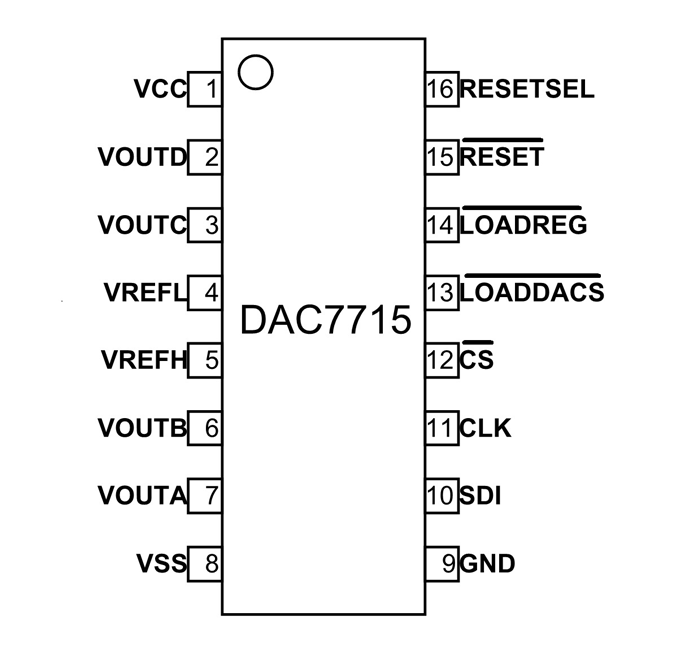
DAC7715 is a 16 pin device as shown in figure and description for each pin is given below.
|
Pin |
Name |
Function |
|
1 |
VCC |
Positive Supply Voltage, +15V nominal |
|
2 |
VOUTD |
DAC D Voltage Output |
|
3 |
VOUTC |
DAC C Voltage Output |
|
4 |
VREFL |
Reference Input Voltage Low, Sets minimum output voltage for all DACs |
|
5 |
VREFH |
Reference Input Voltage High, Sets maximum output voltage for all DACs |
|
6 |
VOUTB |
DAC B Voltage Output |
|
7 |
VOUTA |
DAC A Voltage Output |
|
8 |
VSS |
Negative Supply Voltage, 0V or –15V nominal |
|
9 |
GND |
Ground |
|
10 |
SDI |
Serial Data Input |
|
11 |
CLK |
Serial Data Clock |
|
12 |
CS |
Chip Select Input |
|
13 |
LOADDACS |
All DAC registers become transparent when LOADDACS is LOW. They are in the latched state when LOADDACS is HIGH |
|
14 |
LOADREG |
The selected input register becomes transparent when LOADREG is LOW. It is in the latched state when LOADREG is HIGH |
|
15 |
RESET |
Asynchronous Reset Input. Sets DAC and input registers to either zero-scale (000H) or mid-scale (800H) when LOW. RESETSEL determines which code is active |
|
16 |
RESETSEL |
When LOW, a LOW on RESET will cause the DAC and input registers to be set to code 000H. When RESETSEL is HIGH, a LOW on RESET will set the registers to code 800H |
Features and Electrical Characteristics of DAC7715
- Four output channels
- Low power consumption: 250mw (max)
- Work on single +15V supply or from dual +15V and –15V supplies
- Settling time: 10ms to 0.012%
- 12-bit linearity and Monotonicity at temperature range: –40°c to +85°c
- Double-buffered data inputs
- Small so-16 package
- Maximum supply voltage VCC to GND: +16V
- Maximum supply voltage VCC to VSS: +32V
- Maximum operating temperature: –40°c to +85°c
Similar DAC ICs
DAC8814 and DAC8811
Overview of DAC7715 IC
DAC7715 is basically used in applications where DAC conversion is required and is preferred for small size battery powered application as the chip is in SOIC package and consumes very less power for operation. The chip being capable of working on dual power, comes in handy in some applications. In addition being able to provide four analog outputs by taking in serial input by a single source is preferred in many microcontroller based applications.
How to use DAC7715 Chip
Below is a simple application circuit for DAC7715 which is already given in the datasheet.
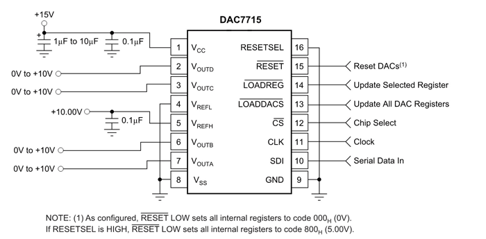
The above circuit is for single supply voltage of +15V and is called Basic Single Supply Operation Circuit. Here VREFH is connected to +10V to give positive reference voltage of +10V to DAC and VREFL is connected to ground to give negative reference voltage of 0V to DAC. With these references the voltages at the four outputs will range from 0V to +10V. Serial data is given in at SDI and Clock is given at Clock pin.
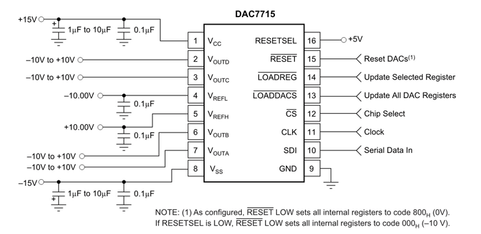
The above circuit is for dual supply voltage of +15V and -15, it is called Basic Dual Supply Operation Circuit. Here VREFH is connected to +10V to give positive reference voltage of +10V to DAC and VREFL is connected to -10V to give negative reference voltage of -10V to DAC. With these references the voltages at the four outputs will range from -10V to +10V. Serial data is given in at SDI and Clock is given at Clock pin.
The digital data is sent through SDI pin bit by bit and once the 12 bit serial data is sent followed by two channel selection bits the LOADDACS pin is pulled low for starting the conversion. The output will be available at set output channel after conversion.
Applications
- Process control
- Ate pin electronics
- Closed-loop servo-control
- Motor control
- Data acquisition systems
- DAC-per-pin programmers
2D-Model
