GT-521F32 - Finger Print Sensor Module
Description of GT-521F32 Sensor
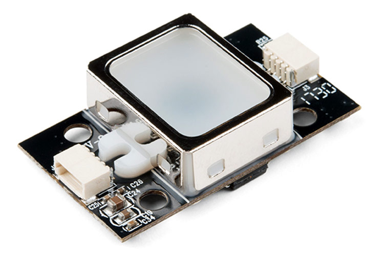
The GT-521F32 fingerprint sensor is an optical sensor with a 258x202 pixel resolution. The sensor module has a 32- bit microcontroller based around the ARM cortex processor core to analyze the data. It can be interfaced with products using the UART communication protocol. The GT module also has a function to be wakened up, when a finger is placed onto the metal frame around the fingerprint sensor.
Features and Specifications of GT-521F32 Sensor
Below are some of the mentioned Features and Specifications of the Fingerprint sensor module:
- Integrated CPU: ARM Cortex M3 core
- Operating voltage: 3.3V-6V
- Maximum operating current: 130mA
- Window Size: 16.9x12.9 (Effective sensor window: 14x12.5)
- Image Size: 258x202 pixel
- Resolution: 450dpi
- Maximum number of fingerprints: 200 fingerprints
- Communication Interface: UART & USB 2.0
- Identification Time: <1.5 sec
Pin Configuration of GT-521F32 Sensor
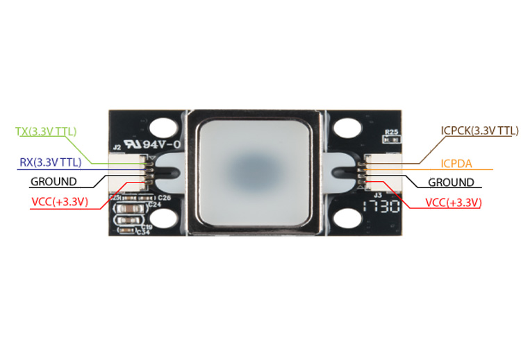
The GT-521F32 sensor module has two connection ports, one for communication (Left side from top view) and the other one for the touch IC connector (Right side from top view).
UART Connector
|
Pin Type |
Description |
|
TX |
Transmitting serial data |
|
RX |
Receiving serial data |
|
GND |
Ground |
|
VCC |
Input Voltage(3.3V-6V) |
Touch IC Connector
|
Pin Type |
Description |
|
VCC |
Input Voltage |
|
GND |
Ground |
|
ICPDA |
Program Mode: In-circuit programming data/address pin |
|
ICPCK |
Program mode:In-circuit programming clock pin Normal mode:It could be the wake-up function from touch IC to VIL |
Alternatives for GT-521F32 Sensor
AS608, SEN0348, SEN0359, R307, R503, Adafruit AT42QT1012
Equivalent of GT-521F32 Sensor
GT-521F52 (Can store up to 3000 fingerprints)
Note: More technical information can be found in the GT-521F32 Datasheet linked at the bottom of this page.
Working of the GT-521F32 Sensor
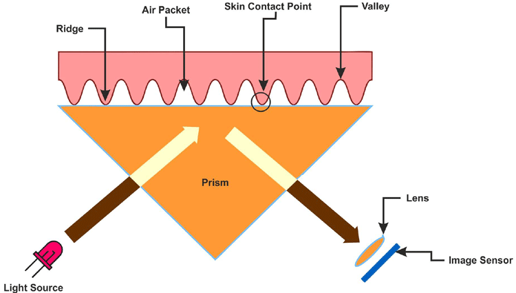
A Fingerprint sensor is an optical sensor. It works by flashing a bright light over your finger and capture a digital picture of your fingerprint. The light-sensitive microchip converts the digital image into a series of 0’s and 1’s by checking the ridges(peaks) and valleys(gaps) of the fingerprint. The series of 1’s and 0’s generated is individual to every person which creates a unique ID for every fingerprint.
Connecting the GT-521F32 sensor with the MCU/MPU
A 4 pin JST-SH connector is used to connect the sensor module to an MCU/MPU. There is a polarity indicator next to the JST-SH connector for a distinction of the pin terminal. The connector breaks out the pins for power and UART communication. You will need a logic level converter or a voltage divider to safely communicate with the 5V device.
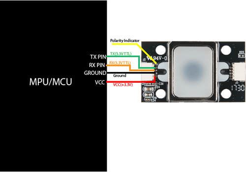
Note: While using the module with a 5V Arduino, make sure to use either a dedicated logic level converter or a voltage divider circuit using resistors.
Touch State Monitoring Statuses
The sensor module has the feature of auto wake up whenever a finger is placed over the window or the metal frame.
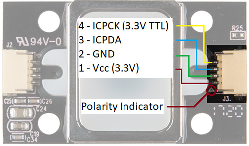
To use this functionality, you need to connect three pins from the Touch IC connector; VCC(+3.3V), Ground, and the ICPCK pin. The ICPCK pin provides an output (Low or High) based upon the placement of the finger onto the touchpad(metal frame). The VCC pin of the GT module can be connected to the 3.3V pin of the microcontroller, the ground pin of the module to the ground of the MCU, and the ICPCK can be connected to any digital pin on the MCU/MPU.
The table below mentions the status of the ICPCK pin after the different positions of the finger placed on the metal case.
|
Touch State |
ICPCK Pin Status |
|
Finger initially touching the metal frame |
Low → High |
|
No finger touching the frame |
Low → Low |
|
Finger touching the frame |
High → High |
|
Removing finger from the frame |
High → Low |
Applications of GT-521F32 Sensor
Here are some of the application where the GT-521F32 sensor can be used:
- Security systems
- School Attendance system
- Home/Office Locks
- Biometrics
- Smartphone unlocking
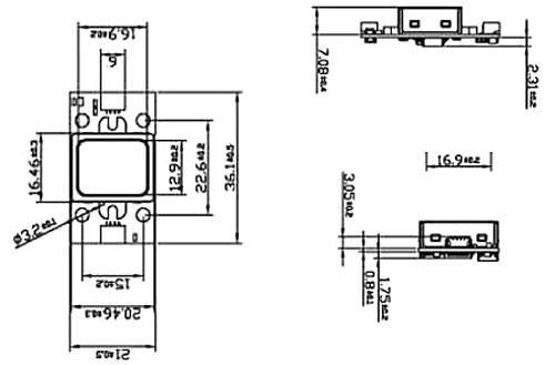
2D model of GT-521F32 Sensor
Below is the 2D model of the GT-521F32 Sensor, All the dimensions are in millimeters. The dimensions can be used to create custom footprints to design your own PCB or CAD models.
