New AC-DC Controller Combined with Inde-Flux Transformer Technology for Simplifying Design, Reducing Size and Cost

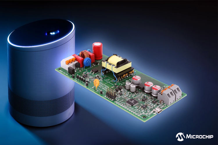
Microchip Technology has introduced a new reference design with the MCP1012 high voltage auxiliary AC-DC controller for removing the independent bias power supply in many applications. The MCP1012 offline auxiliary device enables the system to transfer control of the power and duty cycle to a secondary MCU.
This primary-side auxiliary controller provides for system startup gating and protecting an offline flyback converter for the secondary MCU. The device also offers direct measurement and active regulation of voltage and/or current, high loop bandwidth by direct loop closure, and simplified communication for load-referenced systems. An Inde-Flux technology-based transformer comes with the 15W MCP1012 offline reference design. This combines the signal power and signal communication into one device eliminating the need for optical feedback or an independent signal transformer.
By eliminating the need for an auxiliary power supply on the primary side, the device reduces the complexity of the system including eliminating the need for optocouplers in many applications such as appliances and smart speakers. The 15W MCP1012 offline reference design, part number EV37F82A, is available now for $225.00 each. Microchip also provides a fundamental 1W evaluation board, the DT100118 for $115.00.
Features of 15W MCP1012
- MCP1012 uses an open-loop, constant off-time, peak current-mode current regulator
- MCP1012 uses a high voltage silicon process (0.5µ 5v/30v/700v) to develop a High Voltage (HV) Linear Regulator. The HV Linear Regulator will be rated for 700V, with input at VIN and a regulated bias output at VDD.
- VDD is monitored by the Under-voltage Lockout (UVLO) and Over-voltage Lockout (OVLO) feature
- The device’s internal open-loop, peak current-mode current regulator operates in constant Off-Time mode. The duration of the Off-Time is internally fixed at 20µs typical
- MCP1012 provides a MOSFET Gate Driver (GATE)
- The Gate Driver can be commanded either by the internal open-loop, constant off-time peak current-mode current regulator circuitry, or by an external PWM command via PULSE
Note: More technical information can be found in the MCP1012 Datasheet linked at the bottom of this page and on the MCP1012 15W product page.


