PZEM-004T Energy Meter Module
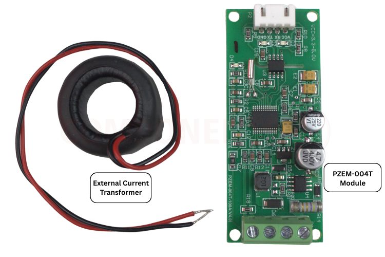
This PZEM-004T V4 is a multi-function AC power monitor module used for measuring the AC voltage, current, active power, frequency, power factor and active energy via a non-invasive Current Transformer(CT) and TTL serial communication. This PZEM-004T energy meter module is built around the SD3004 energy metering IC. The SD3004 is a highly integrated single-phase energy measurement IC designed for AC power monitoring applications. This IC, the PZEM-004T sensor, performs internal analog-to-digital conversion (ADC) and digital signal processing to compute electrical parameters in real time. This PZEM-004T energy meter module can replace the separate voltage and current sensors. It is widely used in energy monitoring, smart metering, IoT-based power analysis and automation applications. You can refer to the PZEM-004T user manual for more details.
V9881D (Single-Phase Energy Monitoring IC)
The IC is manufactured by Vango Technologies, Inc.V98XX is a single-phase energy metering SoC chip, featuring very low power consumption and high performance. It integrates Analog Front-End (AFE), energy metering architecture, enhanced 8052 MCU core, RTC, WDT, Flash memory, RAM, and LCD driver. It can be used for single-phase multi-functional energy meter applications. It is a compact surface-mount IC that performs signal processing and communicates measurement data to a microcontroller via a TTL UART interface. This comprehensive guide covers the complete PZEM-004T datasheet specifications, detailed PZEM-004T pinout configuration, PZEM-004T schematic analysis, wiring instructions, and practical applications. You can refer to the V9881D datasheet for more details.
This compact surface-mount IC integrates:
- Analog Front-End (AFE) for signal conditioning
- Energy metering architecture for accurate power calculations
- Enhanced 8052 MCU core for data processing
- RTC (Real-Time Clock) for timestamping
- WDT (Watchdog Timer) for system reliability
- Flash memory and RAM for data storage
- LCD driver for display applications
PZEM-004T Datasheet: Complete Technical Specifications
The following table provides comprehensive technical specifications from the PZEM-004T datasheet, including measurement ranges, resolution, communication protocol, and operating parameters essential for system integration and application design.
PZEM-004T Energy Meter Module Specifications
| Specification |
Value/Range |
| Model |
PZEM-004T |
|
AC Voltage Measurement |
80-260V AC |
|
Voltage Resolution |
~0.1V |
|
Current Measurement Range |
0-100A |
|
Power Measurement Range |
0-22kW |
|
Energy (kWh) Range |
0-9999kWh |
|
Frequency Range |
45HZ-65Hz |
|
Power Factor Range |
0.00 - 1.00 |
|
Communication Interface |
UART serial |
|
Protocol |
Modbus-RTU style |
|
Operating Supply |
Module typically powered separately(5V DC for logic or as specified) |
|
Operating Temperature |
Typical commercial range |
|
Isolation |
Used a current transformer |
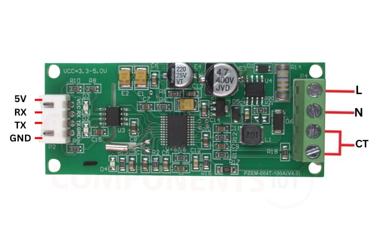
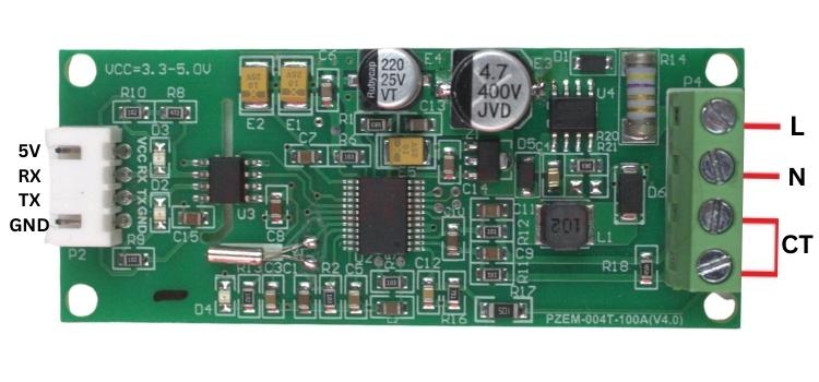
PZEM-004T Pinout: Complete Pin Configuration & Connection Guide
The PZEM-004T pinout includes power pins for supplying the module, UART pins for communication with a microcontroller, AC terminals for sensing mains voltage, and CT terminals for measuring current using a clamp sensor. Understanding the PZEM-004T pinout is crucial for proper integration with microcontrollers and AC power systems. The image below shows the pinout of the PZEM-004T module
|
Pin/Terminal |
Type |
Description |
Connection/Notes |
| VCC | Power |
5V DC supply input |
Connect to 5V |
|
RX |
UART |
Serial receive(TTL) |
Connect to MCU TX |
| TX | UART |
Serial transmit(TTL) |
Connect to the MCU RX |
| GND |
Power |
Ground |
Common ground with MCU |
|
L(Line) |
AC Input |
AC phase/live input |
Connect to the mains live wire |
|
N(Neutral) |
AC Input |
AC neutral input |
Connect to the mains neutral wire |
|
CT+/CT - |
Sensor Input |
Current transformer input |
Connect the non-invasive CT clamp |
PZEM-004T Pinout Connection Best Practices
- Supply Power: Check if you have a stable and regulated 5V DC supply with no shared power lines between high current devices (i.e. relays, solenoids); otherwise, voltage drop will cause problems.
- Communications with UART: Nothing crosses the opposite connection when wiring your UART pins (TX to RX; RX to TX). Ensure you're using 5V logic levels; if you're connecting a 3.3V microcontroller+UART to a 5V-dc UART connection, you will need to use a level shift.
- Wiring & AC Safety: Before working on any AC Wiring or AC work, make sure to cut off the AC power to all circuits. The wire should be of the correct gauge that is rated for the current that it will be carrying. Always follow local electrical codes!
- Clamp Current Transformer: The current transformer must have a properly closed clamp for correct current direction; only one conductor (or live wire) can be closed in the clamp. Follow the directions of polarity to obtain the correct directional flow of current.
- Grounding: Your home and ground must be grounded for safety reasons. All AC grounds must not connect to DC grounds without proper isolation between the two.
Key Electrical Parameters Measured by PZEM-004T Sensor
The PZEM-004T sensor can simultaneously measure:
1. AC Voltage(V)
Suitable for standard single-phase AC mains supply
Measures the RMS value of the line voltage
2. AC Current(A)
No direct electrical contact with the high-voltage line, ensuring safety. The AC Current can be measured using a non-invasive Current Transformer(CT).
3. Active Power(W)
Calculates real power consumed by the load
4. Active Energy(Wh/kWh)
Accumulates energy consumption over time. It is ideal for billing, energy audits, and consumption analysis.
5. Frequency
Measures the supply frequency (typically 50Hz or 60Hz).
6. Power Factor
Indicates the efficiency of power usage.
PZEM-004T Functional Block Diagram & System Architecture
This block diagram represents a complete AC power measurement system designed to safely and accurately monitor electrical parameters. The AC voltage and current from the mains are first sensed using voltage inputs and a current transformer (CT), which allows current measurement without direct electrical contact. The functional block diagram illustrates the complete signal flow and processing architecture of the PZEM-004T energy meter module.
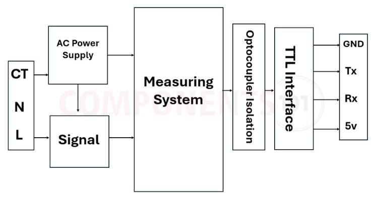
These signals are then fed into a measurement and processing unit, where parameters such as voltage, current, power, energy, frequency, and power factor are calculated. To ensure electrical safety and noise immunity, the processed signals pass through an optocoupler, which provides galvanic isolation between the high-voltage AC side and the low-voltage digital side. Finally, the isolated digital data is sent to a microcontroller via a TTL serial interface, enabling the controller to read real-time power data, display it, store it, or transmit it further for monitoring and control applications.
PZEM-004T Working Principle & Measurement Methodology
Measurement of Voltage
This module directly measures AC voltage using internal circuitry with isolation and scaling. The voltage is internally converted to a digital signal and processed.
Measuring current using a current transformer
Non-invasive split-core current transformers are installed around the live wires. Generates a small current proportional to the charging current. This provides electrical insulation and safe installation.
Internal signal processing
Built-in energy sensing IC processes voltage and current signals. RMS value, power, frequency, and power factor are calculated internally. Energy is accumulated and stored in internal registers. The PZEM-004T sensor utilises a split-core current transformer (CT) that clamps around the live wire without requiring circuit interruption or insulation removal.
PZEM-004T Module Alternatives & Comparison Guide
If you are looking for an alternative for PZEM-004T V4, you can look at the other ICs from these: PZEM-016, HLW8012 Module, ADE7757, ADE7753, CS5460 Module, and INA226. This comprehensive comparison of PZEM-004T module alternatives helps you select the optimal energy monitoring IC or module based on accuracy requirements, communication interfaces, measurement ranges, and application constraints.
PZEM-004T Alternatives Comparison Table
|
Module / IC Name |
Type | Measured Parameters | Current Range | Communication | Accuracy Level | Remarks / Use Case |
| PZEM-016 | AC Energy Module | V, I, Power, Energy | Up to 100 A (CT) | RS485 (Modbus) | ±1% | Industrial-grade alternative |
| HLW8012 Module | Energy Meter IC | V, I, Power, Energy | Depends on CT/shunt | Pulse / UART | ±1–2% | Used in smart plugs |
| ADE7757 | Energy Meter IC | V, I, Power, Energy | External sensors | SPI | High (Class 1) | Professional metering IC |
| ADE7753 | Energy Meter IC | V, I, Power, Energy | External sensors | SPI | High (Utility-grade) | Used in commercial meters |
| CS5460A Module | Energy Meter IC | V, I, Power, Energy | External CT/shunt | SPI | Very High | Industrial & research use |
| INA226 | Power Monitor IC | V, I, Power | External shunt | I²C | Very High | Precision DC monitoring |
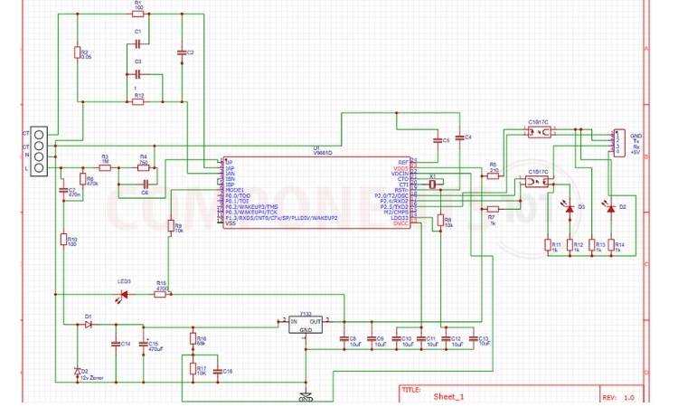
PZEM-004T Schematic Diagram
The PZEM-004T V4 schematic clearly gives the idea that the dedicated energy-metering IC performs voltage, current, power, and energy calculations. The AC line is directly sampled through a resistor divider and RC filtering network to scale and condition the mains voltage for safe measurement.
PZEM-004T Applications in Energy Monitoring & IoT Systems
The versatile PZEM-004T energy meter module serves diverse applications across residential, commercial, and industrial sectors.
- Smart Energy Meters
- Home Energy Monitoring Systems
- Industrial Load Monitoring
- Solar Inverter Output Measurement
- EV Charging Station Monitoring
- Distribution Panel Energy Tracking
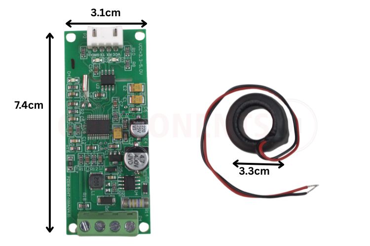
PZEM-004T Dimensions & Physical Specifications
The image shows the PZEM-004T AC energy meter module along with its non-invasive current transformer (CT) clamp, highlighting the compact board size (approximately 7.4 cm × 3.1 cm) and the CT inner diameter (about 3.3 cm).
PZEM-004T Physical Dimensions & Mechanical Specifications
| Component | Dimension | Measurement (mm) | Notes |
| PCB Module | Length | 74mm (7.4cm) | Longest dimension |
| PCB Module | Width | 31mm (3.1cm) | Perpendicular to length |
| PCB Module | Height | ~18mm (1.8cm) | Including components and terminals |
| PCB Thickness | Standard | 1.6mm | Standard FR4 PCB |
| Mounting Holes | Diameter | 3.0mm - 3.2mm | M3 screw compatible |
| Mounting Hole Spacing | Center-to-center | ~65mm × 23mm | Verify with the actual module |
| CT Clamp (Typical) | Inner Diameter | 33mm (3.3cm) | Accommodates wire up to AWG 4/0 |
| CT Clamp (Typical) | Outer Diameter | ~45mm | Total clamp size when closed |
| CT Clamp (Typical) | Cable Length | 1000mm (1m) typical | From CT to the connector |
| Terminal Connectors | Pin Header Pitch | 2.54mm (0.1") | Standard breadboard compatible |
| AC Terminals | Screw Terminal Pitch | 5.08mm (0.2") | Accepts wire up to AWG 14 |
| Weight | Module Only | ~25g | Without a CT clamp |
| Total Weight | Module + CT | ~100g | Complete measurement system |


