ATtiny84 8-bit AVR Microcontroller
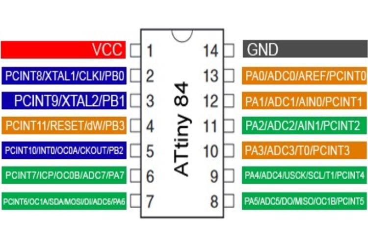
ATtiny84 is high-performance and packed with Microchip's picoPower technology in an 8-bit AVR RISC architecture based Microcontroller unit that has 14 pins, out of which 12 pins can be used as I/O pins.
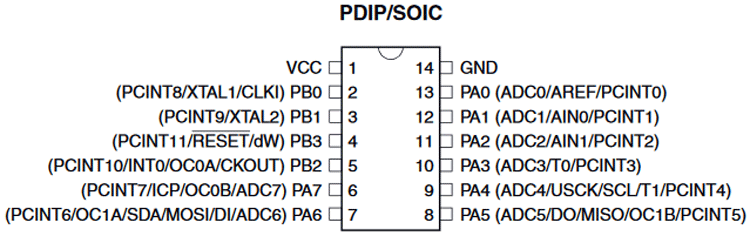
ATtiny84 Pin Configuration
|
Pin Number |
Pin Name |
Description |
|
1 |
VCC |
Positive Pin of MCU (+5V) |
|
2 |
(PCINT8/XTAL1/CLKI) PB0 |
Pin of Port B Bit 0 or Oscillator pin or Pin change interrupt source 8 or Clock input from an external source |
|
3 |
(PCINT9/XTAL2) PB1 |
Pin of Port B Bit 1 or Oscillator pin or Pin change interrupt source 9 |
|
4 |
(PCINT11/RESET/dW) PB3 |
Pin of Port B Bit 3 or Reset pin mainly used for programming or Debug wire enable or Pin change interrupt source 11. |
|
5 |
(PCINT10/INT0/OC0A/CKOUT) PB2 |
Bidirectional I/O Pin of Port B Bit 2 or External Interrupt 0 or System clock out or Pin change interrupt source or Timer/Counter0 Compare Match A Out |
|
6 |
(PCINT7/ICP/OC0B/ADC7) PA7 |
Bidirectional I/O Pin of Port A Bit 7 or ADC Input Channel 7 or TImer/Counter1 Capture or Timer/Counter1 Compare Match B Out or Pin change Interrupt 0, source 7 |
|
7 |
(PCINT6/OC1A/SDA/MOSI/DI/ADC6) PA6 |
Bidirectional I/O Pin of Port A Bit 6 or ADC Input Channel 6 or USI DATA input or SPI MOSI used for ICSP programming or Timer/Counter1 Compare Match A Out or Pin change Interrupt 0, source 6 |
|
8 |
PA5 (ADC5/DO/MISO/OC1B/PCINT5) |
Bidirectional I/O Pin of Port A Bit 5 or ADC Input Channel 5 or USI DATA out or SPI MISO used for ICSP Programming or Timer/Counter1 Compare Match B Out or Pin change Interrupt 0, source 5 |
|
9 |
PA4 (ADC4/USCK/SCL/T1/PCINT4) |
Bidirectional I/O Pin of Port A Bit 4 or ADC Input Channel 4 or USI Clock (Three wire) used for ICSP Programming or I2C SCL or Timer/Counter1 Clock Source or Pin change Interrupt 0, source 3 |
|
10 |
PA3 (ADC3/T0/PCINT3) |
Bidirectional I/O Pin of Port A Bit 3 or ADC Input Channel 3 or TImer/Counter0 Clock source or Pin change Interrupt 0, source 3 |
|
11 |
PA2 (ADC2/AIN1/PCINT2) |
Bidirectional I/O Pin of Port A Bit 2 or ADC Input Channel 2 or Analog Comparator Input - or Pin change Interrupt 0, source 2 |
|
12 |
PA1 (ADC1/AIN0/PCINT1) |
Bidirectional I/O Pin of Port A Bit 1 or ADC Input Channel 1 or Analog Comparator Input + or Pin change Interrupt 0, source 1 |
|
13 |
PA0 (ADC0/AREF/PCINT0) |
Bidirectional I/O Pin of Port A Bit 0 or ADC Input Channel 0 or External Analog Reference Voltage or Pin change Interrupt 0, source 0 |
|
14 |
GND |
Ground Pin of MCU |
Features and Specification of the ATtiny84 Microcontroller
|
ATtiny84 - Simplified Features and Specification |
|
|
CPU |
8-bit AVR |
|
Number of Pins |
14 |
|
Operating Voltage (V) |
1.8-5.5V |
|
Number of I/O pins |
12 |
|
ADC Module |
10-bit (8-Channel) |
|
Timer Module |
8-bit(1), 16-bit(1) |
|
Comparators |
1 |
|
DAC Module |
Nil |
|
Communication Peripherals |
1- SPI, 1-I2C |
|
External Oscillator |
Yes |
|
Internal Oscillator |
8 MHz |
|
Program Memory (KB) |
8 KB |
|
CPU Speed (MIPS) |
20 MIPS |
|
RAM Bytes |
0.5 kB |
|
Data EEPROM |
512 Bytes |
Note: Complete technical details can be found in the ATtiny84 Datasheet, linked at the bottom of this page.
Alternative product of ATtiny84
Alternative products for ATtiny84 microcontroller are listed below-
- ATtiny2313A (Exact Alternative with the new release)
- ATtiny417
- ATtiny28L
- ATtiny48
- ATmega88PA
- ATmega8A
- ATmega8515
- ATmega8535
- ATmega645A
- ATmega6490
Introduction to ATtiny84
ATtiny84 is high-performance and packed with Microchip's picoPower technology in an 8-bit AVR RISC architecture based Microcontroller unit that has 14 pins, out of which 12 pins can be used as I/O pins.
It has Powerful instruction architecture that provides a processing speed of 1 MIPS per MHz while balancing power consumption at the same time processing high-speed performance. The speed could reach up to 20 MIPS if 20 Mhz max frequency is used.
ATtiny84 also comes with the debugWIRE On-Chip debugging feature, In-system Programmable SPI Port, Low-Power Idle, Power-down, and Standby Modes. It also uses a programmable brownout detection circuit as well as an On-chip Temperature Sensor.
It has a wide operating voltage range from 1.8V to 5.5V. Thus it can be used in 1.8V, 3.3V, or 5.0V logic level operations. However, 0-4 Mhz operation is supported by the 1.8V input voltage for ATtiny84V. For frequency up to 10 Mhz, the minimum voltage is required 2.7V for ATtiny84, and for 20 Mhz operations, the minimum voltage is required 4.5V-5.5V. The below image is showing the detailed pin diagram of the ATtiny84.
Detailed Features of ATtiny84
|
ATtiny84 –Detailed Features |
|
|
CPU |
8-Bit AVR RISC |
|
Architecture |
8 |
|
Program Memory Size (Kbytes) |
8 |
|
RAM (bytes) |
512 |
|
EEPROM/HEF |
512 |
|
Pin Count |
14 |
|
Max. CPU Speed (MHz) |
20 |
|
Peripheral Pin Select (PPS) |
No |
|
Internal Oscillator |
8-Mhz |
|
No. Of comparators |
1 |
|
No. Of Operational Amplifier |
0 |
|
No. Of ADC channels |
8 |
|
Max ADC Resolution (bits) |
10bit - 15 ksps |
|
ADC with Computation |
0 |
|
Number of DAC Converter |
0 |
|
Max DAC resolution |
- |
|
Internal Voltage Reference |
No |
|
Zero Cross Detect |
No |
|
No. Of 8-bit timers |
1 |
|
No. Of 16-bit Timers |
1 |
|
Signal Measurement Timer |
0 |
|
Hardware Limit Timer |
0 |
|
No. Of PWM outputs |
4 |
|
Max PWM resolution |
1024 |
|
Angular Timer |
0 |
|
Math Accelerator |
No |
|
No. Of UART module |
0 |
|
No. Of SPI Module |
1 |
|
No. Of I2C module |
1 |
|
No. Of USB Module |
0 |
|
Windowed Watchdog Timer (WWDT) |
No |
|
CRC/Scan |
No |
|
Numerically Controlled Oscillator |
No |
|
Cap. Touch Channels |
6 |
|
Segment LCD |
0 |
|
Minimum Operating Temperature (*C) |
-40 |
|
Maximum Operating Temperature (*C) |
85 |
|
Minimum Operating Voltage (V) |
1.8 / (2.7 up to 10 Mhz) / (4.5 up to 20 Mhz) |
|
Maximum Operating Voltage (V) |
5.5 |
|
High Voltage Capable |
No |
Programming AVR Microcontroller
AVR microcontrollers can be programmed with many different software that is available in the market. There are people who still use Assembly language to program AVR MCUs. The below details is for the most advanced and common software and compiler that has been developed by Atmel (now Microchip) itself.
In order to program the AVR microcontroller, we will need an IDE (Integrated Development Environment), where the programming takes place. A compiler, where our program gets converted into MCU readable form called HEX files.
IDE: Atmel Studio 7
Compiler: AVR and ARM Toolchains
Microchip has given all these two software for free. They can be downloaded directly from their official page. I have also provided the link for your convenience. Once downloaded, install them on your computer. If you have any problem doing so, you can post them in the comment below.
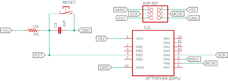
To dump or upload our code into AVR, we will need a device called ATAtmel-ICE. The ATAATmel - ICE programmer/debugger is a simple, in-circuit debugger that is controlled by a PC running Atmel Studio software on a Windows platform. The ATAAtmel-ICE programmer/debugger is an integral part of the development engineer's tool suite. The basic programming circuit for ATtiny84 is shown below.
Other than this official programmer, users also use USB ASP AVR Programming Device for low-cost programming solutions. In addition to this, we will also need other hardware like a Perf board or breadboard, Soldering station, AVR ICs, Crystal oscillators, capacitors, etc.
Components Associated with AVR
USB ASP AVR Programmer, AVR Development Board, Crystal Oscillators, Capacitors, 12V Adapter, 7805 Voltage Regulator
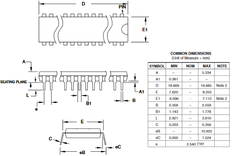
2D Model
The dimensions of the ATtiny84 are shown below-