MAX232
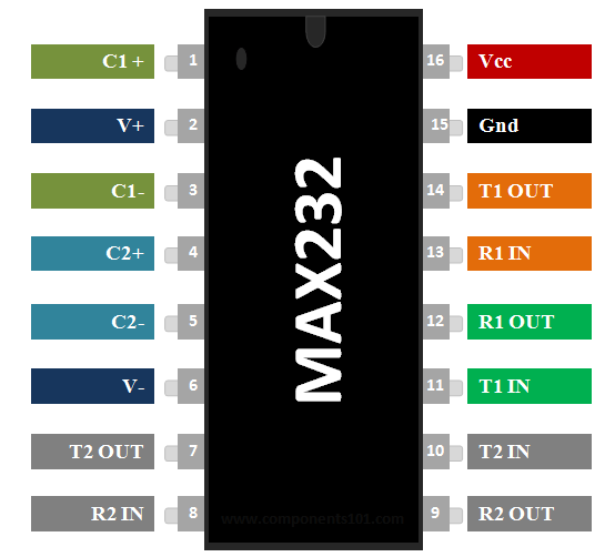
MAX232 Pin Configuration
|
Pin Number |
Pin Name |
Description |
|
1 |
C1 + |
Connects to the positive end of First capacitor |
|
2 |
V+ |
Connects to one end of the capacitor & other end is grounded |
|
3 |
C1 - |
Connects to the negative end of First Capacitor |
|
4 |
C2+ |
Connects to positive end of second capacitor |
|
5 |
C2- |
Connects to negative end of second capacitor |
|
6 |
V- |
Connects to one end of the capacitor & other end is grounded |
|
7 |
T2 OUT |
Transmission pin of second converter module for RS232 cable |
|
8 |
R2 IN |
Reception pin of second converter module for RS232 cable |
|
9 |
R2 OUT |
Reception pin of second converter module for Microcontroller(Rx) |
|
10 |
T2 IN |
Transmission pin of second converter module for Microcontroller(Tx) |
|
11 |
T1 IN |
Transmission pin of first converter module for Microcontroller(Tx) |
|
12 |
R1 OUT |
Reception pin of first converter module for Microcontroller(Rx) |
|
13 |
R1 IN |
Reception pin of first converter module for RS232 cable |
|
14 |
T1 OUT |
Transmission pin of first converter module for RS232 cable |
|
15 |
Ground |
Connects to the ground of the circuit |
|
16 |
Vcc |
Connects to the supply voltage typically +5V |
Features
- TTL/CMOS to RS232 Converter IC
- Can support two conversion at the same time (Dual drivers and Receivers)
- Easy to set-up and initialize
- Operating speed: 120kbit/s
- ±30-V Input Levels
- Operating current: 8mA
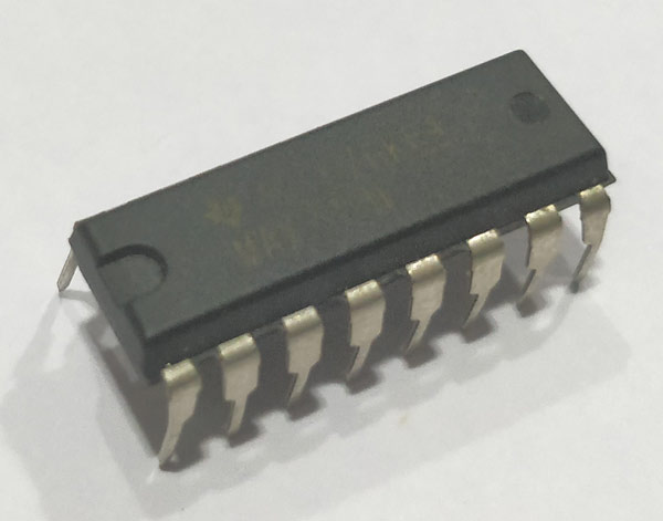
- Available in 16-pin PDIP, SO, SOIC packages
Note: Complete Technical Details can be found in the MAX232 datasheet give at the end of this page.
MAX232 Equivalent RS232 Converters
MC1488, RS232 module, FT232RL, RS232 adapter cable.
Where to use MAX232 IC
IC MAX232 is used for TTL/CMOS to RS232 conversion. Meaning most of our Microcontrollers (PIC/ARM/Atmel) operates on TTL/CMOS logic that is it communicates through either 0V or +5V, but our computers work with the help of RS232 which operates at logic level -24V or +24V. So, if we have to interface these microcontrollers with Computer we need to convert the TTL/CMOS logic to RS232 logic. Hence if you are looking for an IC to perform this conversion and interface a Microcontroller with your computer then MAX232 IC is the right one for you
How to use a RS232 Converter IC
This IC is easy to set-up and can be used easily. The IC work with the help of +5V, hence power the Vcc with +5V and the ground pin to circuit ground. The IC also needs four capacitors to work; these capacitors can be of any value from 1uF to 22uF.
MAX232 IC can help you to convert two logic level conversion that is you can use two Microcontrollers, but to get started we will use only one MCU and connect it to a computer, the complete circuit is to do the same is shown below. As you can see the pins (T2 out, R2 in, T2 in, R2 out) are left free since we are not using the second module.
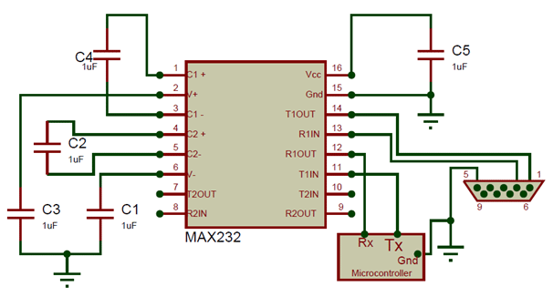
Every microcontroller that has Serial communication capability will have a Tx pin and a Rx pin. These two pins should be connected to the T1 in (pin 10) and the R1 out (pin 13) pin respectively. This is the TTL/CMOS logic inputs, and then the converter RS232 logic signals can be obtained from the pins R1 in (pin 13) and T1 out (pin 14). You might wonder how a 5V signal is being converter to +25V signal when the IC itself is powered with +5V. This is made possible by a method called charge pump, which consists of a capacitor that charges up to provide 25V.
Applications
- Used to Connect Microcontroller with Computers
- TTL/CMOS logic to RS232 converters
- Used in RS232 cables
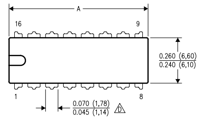
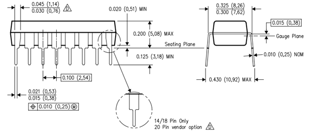
2D Model of MAX 232 (PDIP)