MCP4725 Digital to Analog Converter IC
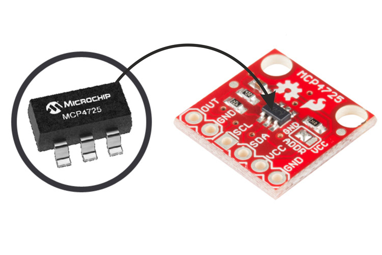
MCP4725 IC from Microchip Technology, is a Single Channel, 12-Bit Digital-to-Analog Converter with integrated EEPROM and an I2C Compatible Serial Interface which is compact in size and has a small footprint. MCP4725 basically converts digital value into analog output voltage. Using MCP4725, we can generally get very precise output voltages. MCP4725 is the most used DAC with Arduino boards. MCP4725 uses I2C communication to connect with Arduino boards.
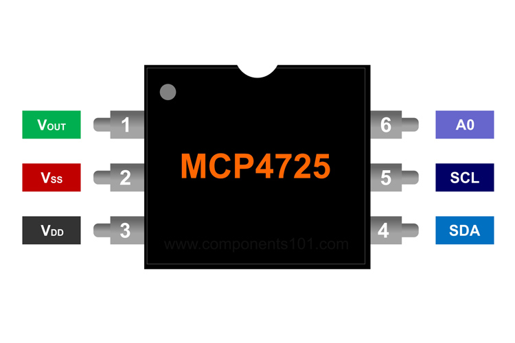
MCP4725 Pinout Configuration
Vout pin is used to collect the analog output. VSS is also the Ground Pin. The DAC reference is driven from VDD. SDA and SCL data pin and clock pin for I2C interface respectively. The A0 pin can be connected to VDD (GND) or VSS (+5V or +3V) according to users’ application.
|
Pin Number |
Pin Name |
Description |
|
1 |
VOUT |
Analog Output Pin |
|
2 |
VSS |
Ground Pin |
|
3 |
VDD |
Reference voltage(Vref) (6.5V max) |
|
4 |
SDA |
Serial data pin for I2C interface |
|
5 |
SCL |
Serial clock pin for I2C interface |
|
6 |
A0 |
External A0 address pin |
Features & Specifications
- On-Board Memory - Non-Volatile (EEPROM)
- 12-Bit Resolution
- External A0 Address Pin
- Has fast Settling Time, around 6µs (typically)
- External Voltage Reference (VDD)
- Has a wide Temperature Range: -40°C to +125°C
- Is compact in size in 6-lead SOT-23 Package
- Can operate in: Standard (100 kbps), Fast (400 kbps) and High Speed (3.4 Mbps) Modes
- Power Consumption is less
- I2C Interface
- Operates under Single-Supply: 2.7V to 5.5V
- Rail-to-Rail Output
- Operates in two mode: Normal or Power-Down
MCP4725 Equivalent
Integrated Industrial Single-Channel DACs: AD5421, AD5420, AD5410, AD5422, AD5412
Integrated Industrial Multichannel DACs: AD5755, AD5735, AD5757, AD5737
Precision DACs: AD5791, AD5781, AD5541A, AD5542A, AD5512A
Transmit IF DACs: AD9148, AD9125, AD9146, AD9117
Note: More technical specifications about MCP4725 Digital to Analog Converter IC can be found in the MCP4725 datasheet attached at the end of this page.
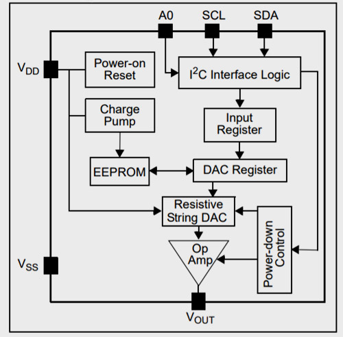
Working or Concept behind MCP4725 IC
The MCP4725 IC has a reference voltage, let’s say 5V (Vref = VDD = 5V) and this reference voltage is divided into 4096 parts (212) and based on the digital value set between 0 and 4095, we can get the accurate analog voltage equivalent. For example, if the reference voltage is 5V, and we set the digital value as 2048, then we get the output voltage as 2.5V because 2048 is half of 4096. It even has a small step size of 1.22mV (5V/4096 = 1.22mV). We can further decrease this if we’re using 3V as reference voltage (and this will give us 3V/4096 = 0.73mV).
MCP4725 breakout board Interfacing with Arduino
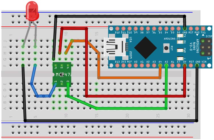
As shown in the circuit, connect VDD (power) to a 5V power supply (5V pin of Arduino Nano) and GND pin of the MCP4725 board to Ground pin of Arduino Nano. These two pins power the MCP4725 breakout board.
Since the DAC uses I2C, the two-pin interface that can give up to 127 unique sensors attached (each must have a different ADDRESS).
Connect SDA pin to I2C Data pin (this is A4 on the Nano and Mega). Connect SCL to I2C Clock pin (this is A5 on the Nano and Mega). These two pin connection is for the I2C communication.
You can alter the I2C address with A0. The address is hex 0x62 by default (nothing linked to A0). The address of A0 when connected to VDD is 0x63. This enables you to connect two DAC boards to the same SDA/SCL I2C bus pins.
VOUT is the DAC's output voltage. Where the DAC value is 0, the voltage will range from 0V to VDD (when the DAC 'value' is the maximum 12-bit number: 0xFFF). Connect this pin to the positive pin of the LED
Finally connect the LED cathode to the Common ground pin.
Upload the given code and after running the code, you can see that the output voltage increases linearly from 0V to 5V DC. This is indicated when the brightness of the LED is linearly increased.
Where to use MCP4725 Digital to Analog Converter IC
MCP4725 is basically a 12 bit Digital to Analog convertor. It is used along with Arduino boards usually because Arduino boards come with built-in ADC but not DAC. Hence, these DACs are used wherever we need a constant analog output. Because of higher (12 bit) resolution provided by MCP4725, it’s very commonly used. It’s small footprint and easy to use features make it very popular. A list of applications of MCP4725 is listed below, although the commonly used area is where PWM signals can’t be generated, where sine wave is required, in dealing with audio projects.
Applications
- Commonly used along with Arduino boards
- Data Acquisition Systems
- Used as DAC for Low Power Portable Instrumentation systems
- To Calibrate Sensors
- Closed-Loop Servo motor control
- Offset Trimming
- Generally used for audio projects and analog projects
- Used in situations where PWM can’t be used
- Used where Sine wave or adjustable bias point is needed
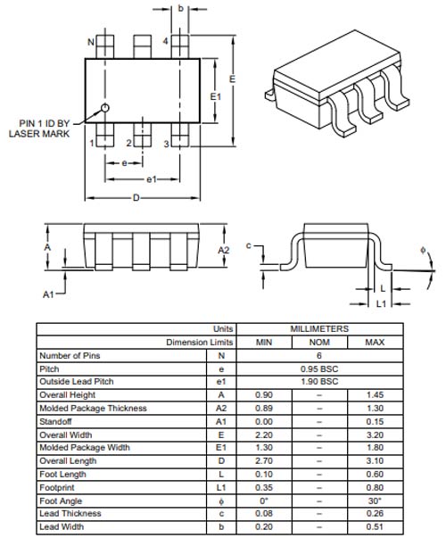
2-D Model and Dimensions