LT111A Voltage Comparator
The LT111A is an improved version of the LM111 general-purpose comparator. LT111A offers maximum input offset voltage of 1.0mV and input offset current of 5nA with a maximum response time of 250ns. The operating voltage range for LT111A is 5V to 15V.
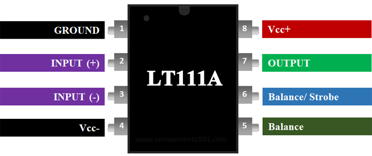
Pin Description of LT111A:
|
Pin Number |
Pin Name |
Description |
|
1 |
GROUND |
Ground pin |
|
2 |
Non-Inverting Input (IN+) |
The Non-Inverting Pin of the comparator gives a variable voltage to compare |
|
3 |
Inverting Input (IN-) |
The Inverting pin is also given a fixed voltage which is compared with the (IN+) |
|
4 |
Ground (VCC-) |
Ground pin connected to the case |
|
5 |
Balance |
This pin can be used to turn off the DC-offset voltage |
|
6 |
Balance/Strobe |
This pin can be used to turn off the output stage |
|
7 |
OUTPUT |
Output Pin |
|
8 |
VCC+ |
Provide the operating voltage for the Op-Amp. For LT111 it is up to +15V |
LT111A Features and Specifications:
- Max Input Offset Voltage: 1.0mV
- Operating Voltage Range: 5V to 15V
- Max Input Offset Current: 5nA
- Max Response Time: 250nS
- Min. Voltage Gain: 200,000
- ±30V Differential Input Voltage
- Drives 50mA Loads At Up To 50V.
Note: Complete Technical Details can be found at the LT111A datasheet give at the end of this page.
Equivalent for LT111A: NTE922, LM311
Alternatives Comparator Op-Amp IC: LM741, LM358, LM339, LM324
Where to use the LT111A Comparator Op-Amp:
The LT111 Differential Comparator Op-Amp is an improved version of LM111 comparator IC from TI that has been used for Voltage comparisons for a long time in electronic designs. The versatility of the LT111A is enhanced by an input stage design which allows differential input signals of up to ±30V. Offset balancing, strobe capability and the ability to "OR" the output is also included.
Any Op-Amp can be made to work as a voltage comparator, but the LT111 proves itself to be advantaged by housing an Output Transistor inside its package. The collector and Emitter pin of this Transistor can also be controlled by the hardware, this makes it’s suitable for many applications.
How to use LT111A:
Like all voltage Comparators, the LT111 also has an Inverting Pin and a Non-Inverting Pin. If the voltage at the Non-Inverting Terminal (pin 2) is high than the Inverting Terminal (pin 2) the output (pin 7) will also be high else the output will be low.
To use the LT111 IC connect the VCC+ (pin 8) to +5V supply voltage and the VCC- (pin 4) to ground to hold it at 0V potential. The pins 5 and 6 on the Op-amp are used to set the balance voltage if you want to manually adjust the DC-Offset voltage. Normally these pins are not used since the Input Offset itself is much better controlled. When not in use the pins 5 and 6 should be shorted.
Applications of LT111A:
- Voltage Comparator circuits
- Can drive Relay, Lamp, Motor Etc
- Zero-Crossing detector
- Peak voltage Detector
- High Voltage protection/Warning
- Oscillator circuits
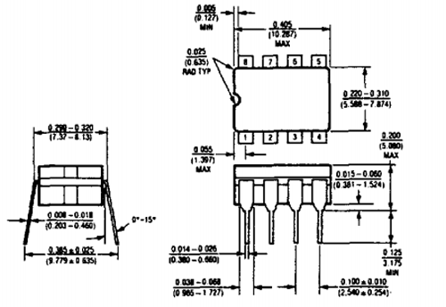
2D-Model of LT111A:
Dimensions for LT111A is given below. These dimensions are for the DIP package.