LM2904 Dual-Operational Amplifiers
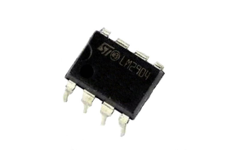
The LM2904 IC consists of two independent, high gain, internally frequency compensated operational amplifiers. LM2904 IC is specifically designed to operate from a single power supply over a wide range of voltages.
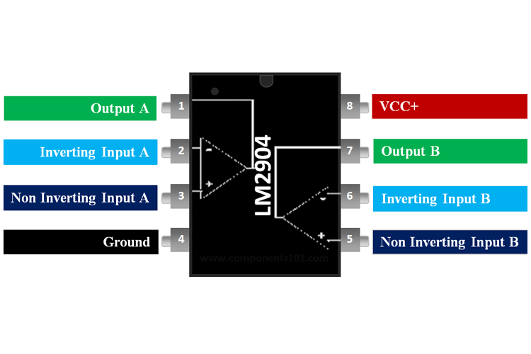
LM2904 Pinout Configuration
|
Pin Number |
Pin Name |
Description |
|
1 |
OUTPUT A |
Output of Op-Amp A |
|
2 |
INPUT A- |
Inverting Input of Op-Amp A |
|
3 |
INPUT A+ |
Non-Inverting Input of Op-Amp A |
|
4 |
GND |
Ground or Negative Supply Voltage |
|
5 |
INPUT B+ |
Non-Inverting Input of Op-Amp B |
|
6 |
INPUT B- |
Inverting Input of Op-Amp B |
|
7 |
OUTPUT B |
Output of Op-Amp B |
|
8 |
VCC |
Positive Supply Voltage |
LM2904 features and specifications
- Supply Voltage: 3V to 26 V
- Operating Supply Current: 250uA
- Output Current per Channel: 30 mA
- CMRR - Common Mode Rejection Ratio: 70 dB
- Ib - Input Bias Current: 250nA
- Vos - Input Offset Voltage: 7 mV
- PSRR - Power Supply Rejection Ratio: 50 dB
- Large DC Voltage Gain: 100 dB
- Wide Bandwidth (Unity Gain): 1 MHz
- Available in 8-Bump DSBGA Chip-Sized Package
Note: Complete Technical Details can be found at the LM2904 datasheet given at the end of this page.
Alternatives Dual Op-Amp IC
LM358, MCP602, RC4558, NE5532, OPA2228, OPA2134 and OPA2604
Where to Use LM2904 IC
The LM2904 is a Dual package version of the commonly used LM741 Op-Amp, both the IC share the same electrical characteristics. This Op-Amp does not have a latch-up problem and hence is ideal to be used in voltage follower applications. It also has internal frequency compensation and short circuit protection in-built and hence requires a minimum number of components to be application ready. Because of these characteristics, these ICs are commonly found inside DVD players and Guitar amplifiers.
LM2904 IC consume very low current. So if you are looking for an Op-amp IC with all these characteristics, then this IC might be right choice for you.
How to Use LM2904 IC
As mentioned earlier this IC requires minimum number of components to be application ready. A high input impedance non-inverting application circuit diagram from LM2904 IC datasheet is shown below.
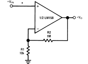
Input supply is given at the non-inverting pin while inverting pin is connected to ground through a 10k resistor. This circuit gives a closed-loop gain equal to the ratio of the sum of R1 and R2 to R1 and a closed-loop 3 dB bandwidth equal to the amplifier unity-gain frequency divided by the closed-loop gain. The gain of the circuit depends on the R1 and R2:
G = 1+ R2/R1
Set R1 to 10kΩ, and R2 to 99x the value of R1, which would be 990kΩ. Replacing the 990kΩ with a 1MΩ will result in a gain of 101, which is within the desired gain tolerance.
Applications of LM2904
- Transducer Amplifiers
- Conventional op-amp circuits
- Integrator, Differentiator, Summer, adder, Voltage follower, etc.,
- DC gain blocks, Digital multimeters, Oscilloscopes
- Comparators (Loop control & regulation)
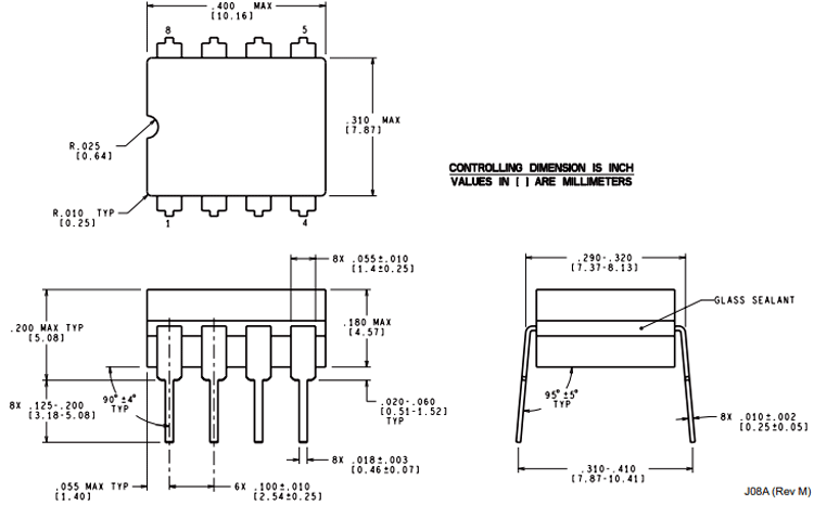
2-D Model of LM2904
Dimensions for LM2904 IC is given below.