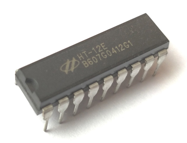
HT12E RF Encoder IC
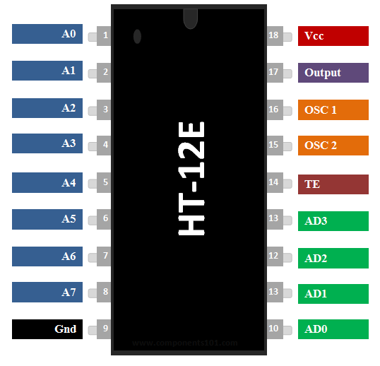
HT12E Pin Configuration
|
Pin Number |
Pin Name |
Description |
|
1 to 8 |
A0,A1,A2,A3,A4,A5,A6 & A7 |
These are the 8-bit address bits, which is used to protect your data. We should set the bits in same pattern on Encoder and Decoder IC to pair them. |
|
9 |
Ground/Vss |
Connected to the Ground of circuit |
|
10 to 13 |
AD0, AD1, AD2 & AD3 |
These four pins are used to send data, the data encoded here will be decoded on HT12D IC sharing the same address bits |
|
14 |
Transmission Enable(TE) |
This pin has to be connected to Ground (0V) to enable the Transmission. |
|
15 and 16 |
Oscillator pins 1 & 2 |
The IC has a built in oscillator. This oscillator can be used by connecting these two pins through a 1M Resistor |
|
17 |
Output |
The Encoded 12 bit output data can be obtained from this pin |
|
16 |
Vcc/Vdd |
This pin powers the IC, typically +5V is used. Can range from 2.4V to 12V |
Features
- 12-bit Encoder IC to be used with HT12D
- Encoded data has 4 Data bits and 8 Address bits (8+4=12-bits)
- Commonly used for RF and IR wireless transmission
- Wide supply voltage range from 2.4V to 12V, typically 5V is used
- Low stand by current of 0.1uA at Vcc=5V
- Available in 16-pin DIP, 20-pin SOP
Note: Complete Technical Details can be found in the HT12E datasheet given at the end of this page.
HT12E Equivalent Encoder
PT2262, 74C922
Where to use HT12E Encoder IC
The IC HT12E can be used only with its pair HT12D. These two ICs together form an Encoder and Decoder pair. They are 12-bit Encoders/Decoders, meaning they can transmit 12-bit a data among them. But your encoder IC should not communicate with someone else decoder IC, so an Encoder and Decoder IC pair will share a common Address which is an 8-bit data. So out of the 12-bits 8-bits will be used to set address and the remaining 4-bit will be used to transmit data. With 4-bit data we can create 16 types (2^4 =16) of combinations. These IC’s are commonly used with RF pairs or IR pairs. So if you are working on a project which has to transmit a 4-bit data from one end to other either by wire or wireless then this IC pair will be best suited for you.
How to use a HT12E Encoder IC
The primary function of HT12E is to encode a 12-bit and send it out through the output pin. Since the IC comes with an in-built Oscillator it is very easy to make this IC work. The IC is has a wide range of operating voltage from 2.4V to 12V, but normally the Vcc pin (pin 18) is powered by +5V and the ground pin (pin 9) is grounded. Pull the Transmission Enable pin (pin 14) to ground to activate transmission. For decoding a data the IC will requires an oscillator, luckily this IC has one in-built. We just have to connect the OSC1 and OSC2 (pin 15 & 16) through a 1M resistor to invoke it. The 4-bit data that has to be sent has to be given to the pins AD0 to AD1 and an address of 8-bit has to be set using the pins A0 to A7. It is very important that your Decoder should also have this same address for them to talk to each other. A basic connection diagram for the HT12E IC is shown below
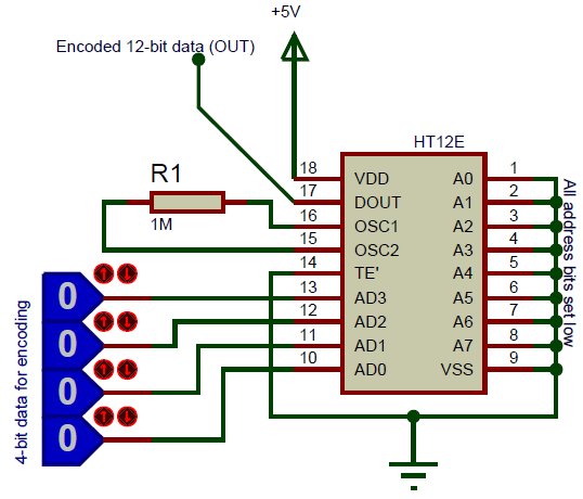
In the above circuit I have set the 8-bit address data as 0b00000000, by connecting all address pins to ground. If you want security you can connect any of the 8 pins to 5V to make it high. The complete IC is powered by a +5V supply which could be obtained from a voltage regulator like 7805.The pins AD3, AD2, AD1 and AD0 are connected to any Digital IC which can provide the 4-bit data. They can also be connected to switches to manually send and receive data. In this image I have made all four data bits as zero (low), when this is decoded we will get the same kind of bits on the output side of HT12D, similarly we can make any changes on these 4-bits and they will be reflected on the output side of the HT12D decoder IC.
The encoded 12-bit can be obtained from the Dout pin (pin 17). This data should be sent to the HT12D for decoding, it can either be sent directly through a wire or by using a wireless medium like RF or IR. You can know to set up the HT12D after this from here.
Applications
- Used to convert Parallel 4-bit data to series data
- Highly useful in wireless communication projects involving RF or IR
- Remote controlled systems like garage doors, Car alarm system, Car door controls, etc.
- Can be used in Home automation for short range remote switching
- Safety systems like Burglar alarm system, Smoke or Fire alarm system etc..
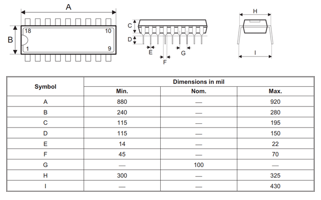
2D Model of HT12E (DIP)