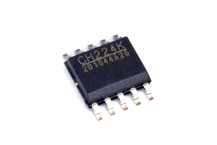
CH224K Low-cost USB-PD Sink Controller
Nowadays USB PD (Power Delivery) is the standard on most modern consumer products. This enables users to use a single power adaptor across various products making it much more economic. CH224K from WCH is an easy-to-use low-cost solution for integrating USB PD into developing products. It offers easy configuration and cost-effective design. CH224K is a PD source controller that will communicate with PD sources such as PD charges and negotiate the necessary power output up to 20V 5A. It supports PD3.0/2.0, BC1.2 and other boost fast charging protocols. It also supports the automatic detection of VCONN and analog E-Mark chips, with a maximum power of 100W. It also has features such as built-in PD communication module output voltage detection, over-temperature protection and over-voltage protection.
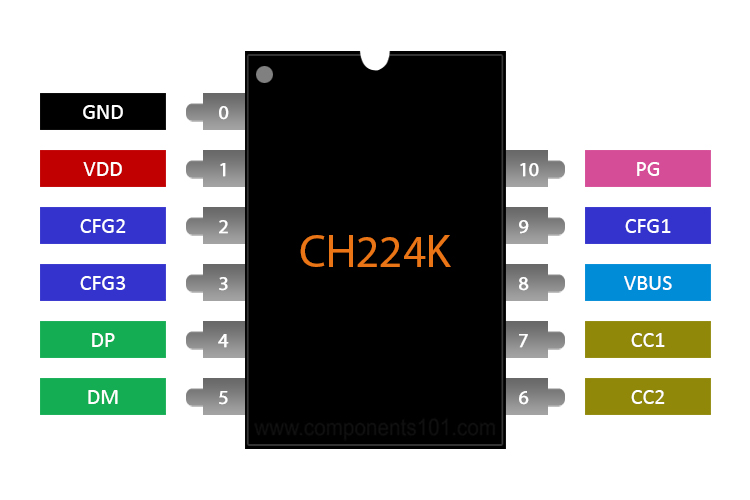
CH224K Pinout Configuration
|
Pin Number |
Pin Name |
Type |
Description |
|
0 |
GND |
Power |
Common Ground |
|
1 |
VDD |
Power |
Power Input |
|
4,5 |
DP, DM |
Communication |
USB Pins |
|
6,7 |
CC1, CC2 |
Communication |
Type-C CC Pins |
|
2,3,9 |
CFG1, CFG2, |
Configuration |
Configuration Pins |
|
CFG3 |
|||
|
8 |
VBUS |
Sense Input |
Voltage sense input |
|
10 |
PG |
Output |
Power Good Pin |
Note: The Complete Technical Details can be found in the CH224K datasheet given at the end of this page.
Equivalent for CH224K: CH224D
Alternatives for CH224K: CH221K, IP2721
Features
- Supports 4V to 22V input voltage
- Support PD3.0/2.0, BC1.2 and other fast charging protocols
- Support USB Type-C PD, support positive and negative insertion detection and automatic switching
- Support E-Mark simulation, automatically detect VCONN, support PD request of 100W power
- The requested voltage can be dynamically adjusted through several methods
- High single-chip integration, simplified peripherals, and low cost
- Built-in overvoltage protection module, overtemperature protection module
How to use the CH224K?
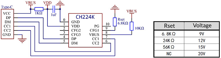
We can use CH224K in stand-alone mode without any co-processor. The power output can be programmed using the config pins. There are two ways to set the output voltage. Method once uses a single configuration pin to set the output. The value of the resistor connected to the config pin CFG1 will determine the output voltage. This method is useful for stand-alone applications. You can find the application schematics below.
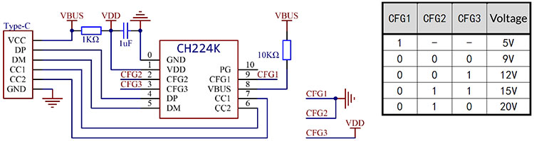
Method 2 can be used for stand-alone applications as well as for controlling it with a microcontroller. This method uses all three config pins CFG1, CFG2 ,CFG3. The state of config pins will determine the output voltage. You can find the schematics for the second method below.
Applications
- Wireless charger
- laptop charging cable
- Lithium battery small appliances
- Lithium battery electric tools
- mobile power
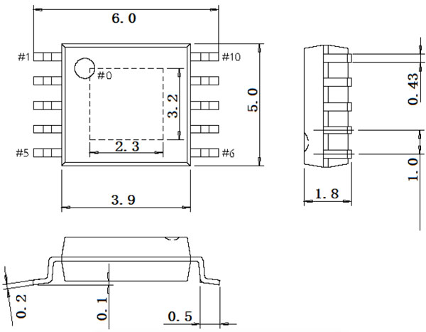
2D Model and Dimensions