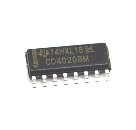
CD4020B 14-bit Binary Counter/Divider
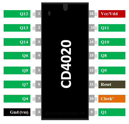
CD4020B IC Pinout Configuration
|
Pin Number |
Pin Name |
Description |
|
1,2,3,4,5,6,7,9,12,13,14,15 |
Q1,Q4,Q5,Q6,Q7,Q8,Q9,Q10,Q11,Q12,Q13,Q14 |
Output pins of the Binary counter |
|
8 |
Ground |
Connected to digital Ground |
|
10 |
Clock |
Clock signal should be given as input |
|
11 |
Reset |
Pulling the reset pin high will reset counter |
Features
- 14-bit Binary Counter/Divider
- Counting range: 0 to 16383 (In decimal)
- Operating Voltage: 3V to 18V
- Nominal Voltage: 5V, 10V, 15V
- Source current, sink current details are given in datasheet below.
- Maximum Clock Frequency: 3.5MHz at 5V
- Reset Propagation Delay: 140ns at 5V
- Available in 16-pin PDIP, CDIP,SOIC, TSSOP packages
Note: Complete Technical Details can be found in the CD4020B datasheet given at the bottom of this page.
Alternatives Binary Counters
CD4024B(7-bit), CD4024B(12-bit)
CD4020 Equivalents
Where to use CD4020 IC?
The IC CD4020 is a 14-bit Binary Counter IC from Texas Instruments. It has 12 output pins ranging from Q1 to Q14 excluding Q2 and Q3. When an Input clock pulse is given to the pin for each pulse, the binary value gets incremented from 00 0000 0000 0000 to 11 1111 1111 1111 which is equivalent for 0 to 16383 in decimal.
This behavior of the IC can be used to build counters and Dividers, also it is very commonly used for timing related applications. So if you are looking for a 14-bit binary counter which can be incremented through a clock pulse then this IC might be of interest to you.
How to use a CD4020 Binary Counter?
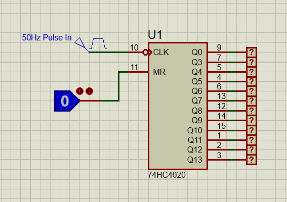
Using the CD4020 binary counter IC is pretty simple. Just power the IC through the Vss and Ground pins, it has a wide operating voltage from 3V to 18V, but typically 5V is used. Once the IC is powered, all the binary outputs will be zero, then the binary value can be incremented by providing a clock pulse to clock pin. For each clock signal, the binary value gets incremented by one. To reset the counter, the Rest pin can be pulled high. The working of the IC is show in gif image below.
As you might have noticed on the output side, we will be missing the Q2 and Q3 pins, these pins are present internally and are not user accessible to keep the package small. These IC’s are commonly used for creating time delays as small as 1ms to even 2 hours or more. For example let us assume an Astable clock input with a frequency of 1Hz from a 555 timer is connected to clock pin. Then the output pins will go high at the following time intervals shown in table below-
|
Output pin to go High |
Turns on at pulse |
Turns on at time interval (approx) |
|
Q1 |
1 |
1 second s |
|
Q2 |
2 |
2 seconds |
|
Q3 |
4 |
4 seconds |
|
Q4 |
8 |
8 seconds |
|
Q5 |
16 |
16 seconds |
|
Q6 |
32 |
Half a minute |
|
Q7 |
64 |
1 minute |
|
Q8 |
128 |
2 minutes |
|
Q9 |
256 |
4 minutes |
|
Q10 |
512 |
8 minutes |
|
Q11 |
1024 |
16 minutes |
|
Q12 |
2048 |
Half an hour |
|
Q13 |
4096 |
1 hour |
|
Q14 |
8192 |
2 hours |
Similarly by varying the clock signals we can obtain shorter or longer time intervals. This comes in very hand in timing applications, frequency counters etc. Once the binary counter has reached to maximum value it will overlap from 0 again, it is also possible to cascade more than one binary counter for higher decimal counting.
Applications
- Used for creating long timing period
- Astable frequency divider or counter circuit
- Timing related applications
- Used in project where Microcontrollers should be avoided
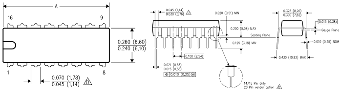
2D Model and Dimensions