AD8324ACPZ - 3.3 V Differential Line Driver IC
The AD8324 is a low-cost amplifier designed for coaxial line driving. The features of the AD8324 are best suited for DOCSIS 2.0 and EuroDOCSIS applications. The gain of the AD8324 is digitally controlled which has an 8-bit resolution over 59dB range, resulting in gain changes of 1 dB/LSB. The AD8324 accepts a differential or single-ended input signal. The output is specified for driving a 75 Ω load through a 1:1 transformer. Distortion performance of –54 dBc is achieved with an output level up to 61 dBm at 65 MHz bandwidth. This device has a sleep mode function that reduces the quiescent current to 30 μA and a full power-down function that reduces the power-down current to 2.5 mA with a supply voltage of 3.3V.
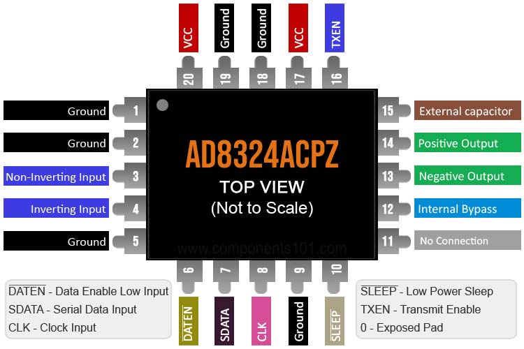
AD8324ACPZ Pinout Configuration
|
Pin No |
Pin Name |
Description |
|
1, 2, 5, 9, 18, 19 |
Gnd |
Common External Ground Reference |
|
3 |
VIN+ |
Non-inverting Input, DC-biased to approximately VCC/2. Must be ac-coupled with a 0.1 μF capacitor |
|
4 |
VIN– |
Inverting Input, DC-biased to approximately VCC/2. Must be ac-coupled with a 0.1 μF capacitor |
|
6 |
|
Data Enable Low Input, This port controls the 8-bit parallel data latch and shift register. A Logic 0 to Logic 1 transition transfers the latched data to the attenuator core (updates the gain) and simultaneously inhibits serial data transfer into the register. A Logic 1 to Logic 0 transition inhibits the data latch (holds the previous and simultaneously enables the register for serial data load). |
|
7 |
SDATA |
Serial Data Input, This digital input allows an 8-bit serial (gain) word to be loaded into the internal register with the most significant bit (MSB) first. |
|
8 |
CLK |
Clock Input, The clock port controls the serial attenuator data transfer rate to the 8-bit master-slave shift register. Logic 0 to Logic 1 transition latches the data bit, and a Logic 1 to Logic 0 transfers the data bit to the slave. This requires the input serial data-word to be valid at or before this clock transition. |
|
10 |
|
Low Power Sleep Mode, In sleep mode, the supply current of the AD8324 is reduced to 30 μA. A Logic 0 powers down the device (high ZOUT state), and a Logic 1 powers up the device. |
|
11 |
NIC |
No Internal Connection, Do not connect to this pin |
|
12 |
BYP |
Internal Bypass, This pin must be externally decoupled (0.1 μF capacitor). |
|
13 |
VOUT- |
Negative Output Signal, Must be biased to VCC. |
|
14 |
VOUT+ |
Positive Output Signal, Must be biased to VCC |
|
15 |
RAMP |
External RAMP Capacitor (Optional) |
|
16 |
TXEN |
Transmit Enable, Logic 0 disables forward transmission, and Logic 1 enables forward transmission |
|
17,20 |
VCC |
Common Positive External Supply Voltage. |
|
0 |
EPAD |
Exposed Pad, The exposed pad must be connected to a solid copper plane with low thermal resistance. This applies to the 20-lead LFCSP package only. |


Features & Specifications
- Supports DOCSIS 2.0 and EuroDOCSIS for reverse path transmission systems
- Gain programmable in 1 dB steps over a 59 dB range
- Low distortion at 61 dBmV output
- Output noise level at minimum gain 1.3 nV/√Hz
- Maintains 75 Ω output impedance in transmit-enable and
- Upper bandwidth of 100 MHz (full gain range)
- Supports SPI® interfaces
- Supply Voltage, VCC 3.63 V
- Input Voltage 1.5 V p-p
- DATEN, SDATA, CLK, SLEEP, TXEN −0.5 V to +3.63 V
- Internal Power Dissipation 776 mW
- Operating Temperature Range −40°C to +85°C
- Available Packages 20-Lead QSOP, and 20-Lead LFCSP
Note: Complete technical details can be found in the AD8324ACPZ datasheet given at the end of this page.
Equivalent IC’s alike AD8324ACPZ Line Driver
DS8921, MT3608, DRV632, DRV135, AM26LS33
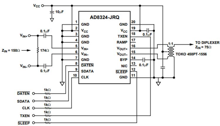
How to use AD8324ACPZ Line Driver IC
The AD8324 is primarily intended for use as the upstream power amplifier (PA) in Data-Over-Cable Service Interface Specification (DOCSIS) certified cable modems and CATV set-top boxes. The upstream signal is either a quadrature phase-shift keying (QPSK) or a quadrature amplitude modulation (QAM) signal generated by a digital signal processor (DSP), a dedicated QPSK/QAM modulator, or a digital-to-analog converter (DAC). In all cases, the signal must be low-pass filtered before it is applied to the PA in order to filter out-of-band noise and higher-order harmonics from the amplified signal.
Due to the varying distances between the cable modem and the headend, the upstream PA must be capable of varying the output power by applying gain or attenuation. The ability to vary the output power of the AD8324 ensures that the signal from the cable modem has the proper level when it arrives at the headend. The upstream signal path commonly includes a diplexer and cable splitters. The AD8324 is designed to overcome losses associated with these passive components in the upstream cable path.
The AD8324 is composed of three analog functions in the transmit enable mode. The input amplifier (preamp) can be used in a single-ended or differential configuration. If the input is used in the differential configuration, ensure that the input signals are 180° out of phase and of equal amplitude. A vernier is used in the input stage for controlling the fine 1 dB gain steps. This stage then drives a DAC that provides the bulk of the attenuation for the AD8324. The signals in the preamp and DAC blocks are differential to improve the power supply rejection ratio (PSRR) and linearity. A differential current is fed from the DAC into the output stage. The output stage maintains 75 Ω differential output impedance in all power modes.
Applications
- DOCSIS 2.0 and EuroDOCSIS cable modems
- CATV set-top boxes
- CATV telephony modems
- Coaxial and twisted pair line drivers
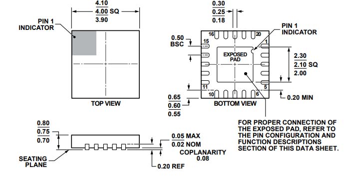
2D Model and Dimensions
If you are designing a PCB or Perf board with this component then the following picture from the Datasheet will be useful to know its package type and dimensions.