IC 4047: CMOS Low Power Monostable/Astable Multi-vibrator
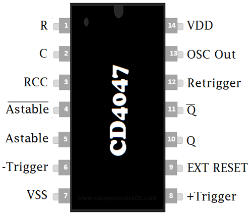
Pin Configuration
|
Pin No. |
Pin Name |
Description |
|
1 |
C |
Used to connect external capacitor |
|
2 |
R |
Used to connect external resistor |
|
3 |
RCC |
Common pin for connecting resistor and capacitor to it |
|
4 |
AST’(Astable bar) |
Low when used in Astable mode |
|
5 |
AST |
High when used in Astable mode |
|
6 |
-Trigger |
When used in Monostable mode we give High to Low transition to this pin |
|
7 |
Vss |
Ground pin of IC |
|
8 |
+Trigger |
When used in Monostable mode we give Low to High transition to this pin |
|
9 |
EXT RESET |
It’s an external reset pin. By giving a high pulse to this pin, it resets the output Q to low and Q’ to high |
|
10 |
Q |
Give normal high output |
|
11 |
Q’ |
Inverse output of pin 10, means it gives low output |
|
12 |
Retrigger |
Used in Monostable mode to simultaneously retrigger +trigger and –trigger pin |
|
13 |
OSC Out |
Gives oscillated output |
|
14 |
Vdd |
Positive input pin of IC |
Features
- Power Consumption is low
- Provide Monostable (one-shot) and Astable (free running) operation
- High noise immunity
- Only one resistor and capacitor required externally
- Standardized, symmetrical output characteristics
Monostable Features
- Retriggerable option for pulse width expansion
- Positive and negative edge trigger
- Output pulse width independent of trigger pulse duration
Astable Features
- Free running operating modes
- 50% duty cycle
- Oscillator output available
- Astable frequency stability is good
Technical Specification
- Wide range of supply input: 3v to 18v
- Operating temperature range: −55°C to +125°C
- Storage temperature range: −65°C to +150°C
- DC input current: ±10mA
- Soldering Lead temperature: 260°C ( for 10s max)
Note: Complete technical information can be found in the 4047 IC Datasheet linked at the bottom of this page.
Where to use 4047 IC?
We can use the IC in both Astable and Monostable mode, for making different circuit. The IC can be used for generating clock pulse, sine wave, square wave and many others. It can also be used in application of timing delay circuits, frequency multiplier and frequency divider. To generate an envelope signal from the original signal this IC is helpful.
How to use 4047 IC?
It needs an external resistor to be connected between PIN 1 and 3 to determine the output pulse width in Monostable mode. For determining Output frequency in Astable mode, it needs a capacitor to be connected between PIN 2 and 3.
Astable mode
If you want to use the IC in Astable mode, you need to HIGH the PIN 5 and LOW the PIN 4. So that you will be able to get constantly fluctuating output between HIGH and LOW. Here, the circuit is given below for Multivibrator in Astable mode:
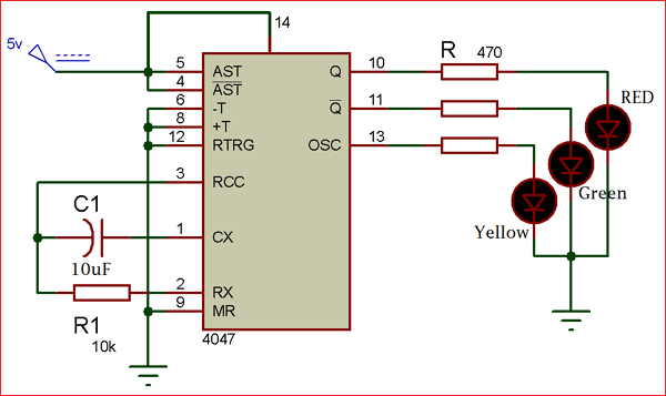
The formula for finding the value of oscillated output frequency (from PIN 13) mathematically is:
OSC Out Frequency= 1 / 4.4RC
Formula for finding the pulse duration is:
t = 2.48RC
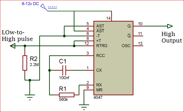
Monostable mode
If you want to use the IC in Monostable mode you have to use the +trigger and –trigger PIN. By giving Low to High transition at +trigger PIN and High to Low transition at –trigger PIN you wil be able to get a Monostable output. The circuit is given below to use the IC in Monostable mode:
The formula for finding the value of frequency mathematically at PIN 11 and 10 is:
F = 1 / 8.8RC
Applications
- Frequency discriminators
- Timing circuits
- Time-delay applications
- Envelope detection
- Frequency multiplication
- Frequency division
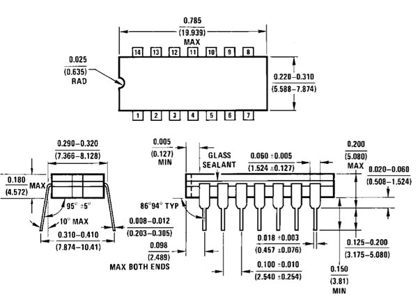
2D-Model and Dimensions