WS2812B Addressable RGB LED
The WS2812B Addressable RGB LED is extremely flexible, easy-to-use, and can be controlled separately. These LEDs are equipped with an integrated driver that allows users to control the color and brightness of each LED independently.
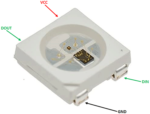
WS2812B LED Pinout Configuration
|
Pin Number |
Pin Name |
Description |
|
1 |
VDD |
LED power supply pin |
|
2 |
DOUT |
Data signal output pin |
|
3 |
GND |
Ground reference supply pin |
|
4 |
DIN |
Data signal input pin |
WS2812B LED Specifications
- Supply voltage - 3.5V to 5.3V
- Signal input voltage - 0.5V to VCC + 0.5V
- Input capacitance - 15pF
- Signal supply current - 1uA
Note: Complete technical details can be found in the WS2812B Datasheet linked at the bottom of this page.
Alternate Addressable RGB LEDs
WS28212, WS2813, APA-109B
Understanding the WS2812B Addressable RGB LED
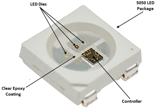
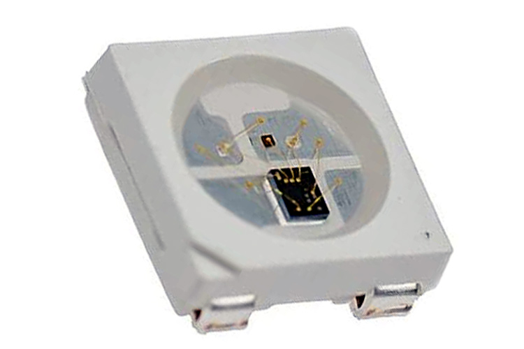
WS2812B comprises three LEDs (red, green, and blue) along with a controller in the same package. The controller contains a 24-bit register, which takes in serial data from the DIN pin and stores and displays it on the respective LED.

The 24-bit register is divided into three parts, each one is 8 bits long and holds a different brightness value for each color. Since there are 8 bits, there can be 256 possible brightness values for each LED. As there are three colors, a total of close to 17 million colors are possible.
The data pins on the LED are designed to be daisy-chained; the output of the controller is buffered to maintain signal quality even if a lot of LEDs are connected.
How to use the WS2812B Addressable RGB LED
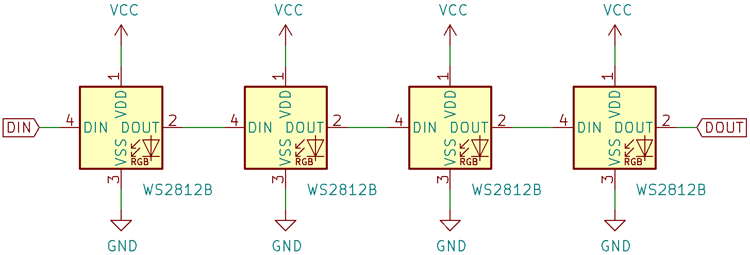
Each LED has an independent VCC, GND, DIN, and DOUT pin. The VCC and GND pins are common to all the LEDs, whereas the DIN of the first LED is connected to the signal source, which could be a microcontroller. The DOUT of the first LED is connected to the DIN of the second LED, and so on, as shown in the diagram below.
WS2812B needs precise data input signals to work properly.
The figure below shows the timing for writing 0 and 1 to each bit in the register and a reset pulse which acts as settling time.
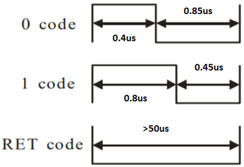
WS2812B uses pulse width modulation to differentiate between 0 and 1. 1 requires a longer pulse width, whereas the 0 requires a shorter pulse width. The total pulse width is 1.25μs, which means that the frequency is 800kHz, with the respective duty cycles for 0 and 1 being 36% and 64%. The tolerance for each pulse width is ±150ns. The reset pulse should be 50 microseconds or longer before the next set of data is sent to the LED.
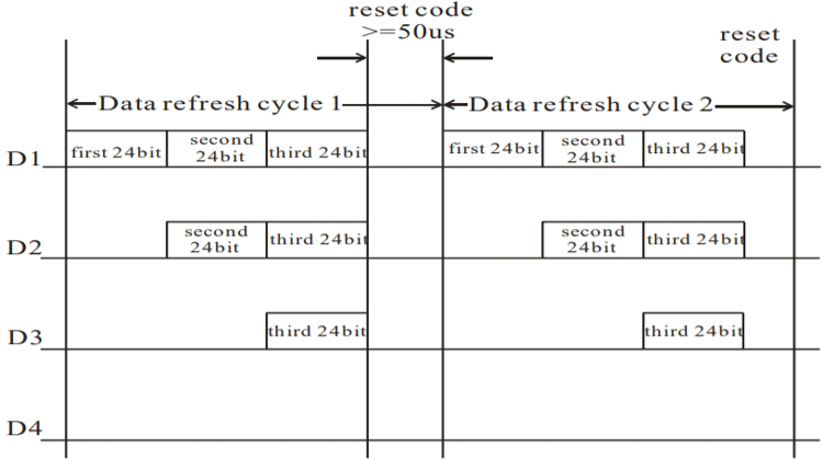
The LEDs should be addressed in order - The first 24 bits to the first LED, the second 24 bits to the second LED, and so on, till all the LEDs in the chain have been addressed. After the first set of data is sent, there should be a blank pulse of 50 microseconds or more to give the LED time to settle, and then the second set of data can be sent. The timing diagram is shown below.
WS2812B Addressable RGB LED Basic Troubleshooting
If the LED does not turn on:
- Check the supply voltage
- Check to see if the dies inside the clear epoxy case look black, it means the LED has been damaged.
- Check if the data lines have been connected correctly and that the required signal and timing is present.
WS2812B Addressable RGB LED Applications
- RGB Lighting strips
- Indicator LED
- Decorative displays
- Backlighting
- General-purpose illumination
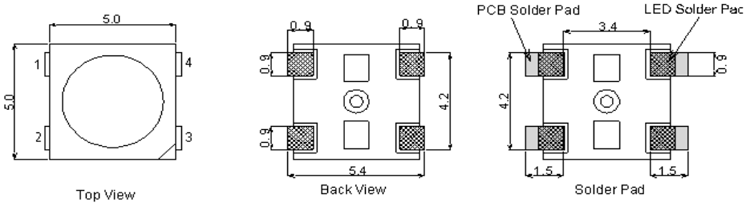
2D Model of the WS2812B LED
The dimensions of the WS2812B LED are given below to help you in selecting the right PCB footprint for WS2812B.