ESP32C3 Mini Development Board
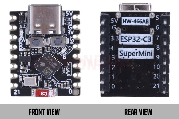
The ESP32-C3 Super Mini is an ultra-compact, thumb-sized ESP32C3 Mini development board powered by Espressif's single-core ESP32-C3 RISC-V SoC. Featuring integrated 2.4 GHz Wi-Fi 4 and Bluetooth 5 (LE), native USB-C connectivity, and a breadboard-friendly form factor measuring just 22.5 mm × 18 mm, this board is particularly well suited to space-constrained applications where wireless connectivity, low power consumption, and a small physical footprint are important.
This article covers the ESP32-C3 Super Mini pinout, technical specifications, the confusion surrounding various commercial market names (Super Mini vs. Pro Mini), how to get started with ESP32C3 programming in Arduino IDE and how it compares with the Xiao ESP32-S3.
Technical Specifications
| Parameter | Specification |
| Microcontroller |
Espressif ESP32-C3 (Single-Core 32-bit RISC-V RV32IMC) |
| Clock Speed | Up to 160 MHz |
| Internal SRAM | 400 KB SRAM + 384 KB ROM + 8 KB RTC SRAM |
| Flash Memory | 4 MB Quad SPI Flash (Embedded / SiP) |
| Wi-Fi | IEEE 802.11 b/g/n (2.4 GHz, up to 150 Mbps) |
| Bluetooth | Bluetooth 5.0 Low Energy (BLE) & Bluetooth Mesh |
| Input Voltage (Power) |
5.0 V via USB Type-C or 5V pin (3.3 V to 6.0 V Max) |
|
Onboard LDO Regulator |
3.3V Low-Dropout Regulator (typically LP5907 / ME6211 series) |
| Current Consumption | Active RF: ~80–240 mA; Light Sleep: ~1.3 mA; Deep Sleep: ~5 µA |
| Total GPIO Pins | 13 user-accessible GPIOs on headers (GPIO0 to GPIO10, GPIO20, GPIO21) |
| ADC Channels | 6 channels (12-bit SAR ADC: ADC1_CH0–CH4, ADC2_CH0) |
| Hardware Interfaces | 1× SPI (FSPI/SPI2), 1× I2C, 2× UART, 6× PWM (LEDC), 1× I2S |
| USB Interface | Native USB Serial/JTAG Controller (USB CDC via Type-C connector) |
| Onboard Indicators & Controls | Power LED (Red), User LED (Blue/Green on GPIO8), BOOT Button (GPIO9), RESET Button |
| Antenna Type | Onboard Ceramic Chip Antenna (Super Mini) / Ceramic + IPEX (Pro Mini) |
| Dimensions | 22.5 mm × 18.0 mm × 4.5 mm (0.88" × 0.71" × 0.18") |
| Pin Pitch |
2.54 mm (0.1") standard breadboard pitch |
For register-level timing, electrical characteristics, and RF certification details, refer to Espressif's official ESP32-C3 Series datasheet and the ESP32-C3-MINI-1/1U module datasheet, both published directly on Espressif's documentation portal.
Pinout & Pin Configuration
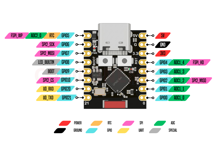
The ESP32-C3 Super Mini breaks out 16 pins arranged in two 8-pin rows with standard 0.1" (2.54mm) pitch, making it fully breadboard-compatible.
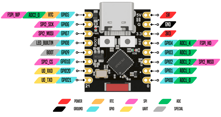
GPIO9 is internally pulled HIGH and is used to enter Download Bootloader Mode when pulled LOW during reset or power-up. Although it functions as a normal GPIO during runtime, it is recommended to avoid using GPIO9 for general-purpose applications whenever possible, especially for external circuits that may drive it LOW during startup, because doing so can unintentionally place the ESP32-C3 into bootloader mode instead of starting the application normally.
GPIO8 controls the onboard user LED and is also a strapping pin involved in flash-voltage and boot configuration. It is therefore best to avoid using GPIO8 for external peripherals whenever possible, particularly if the connected circuit can pull the pin LOW during power-up. Doing so may interfere with the boot configuration and prevent reliable startup. The onboard LED uses active-LOW logic, meaning writing LOW turns the LED ON, while writing HIGH turns it OFF.
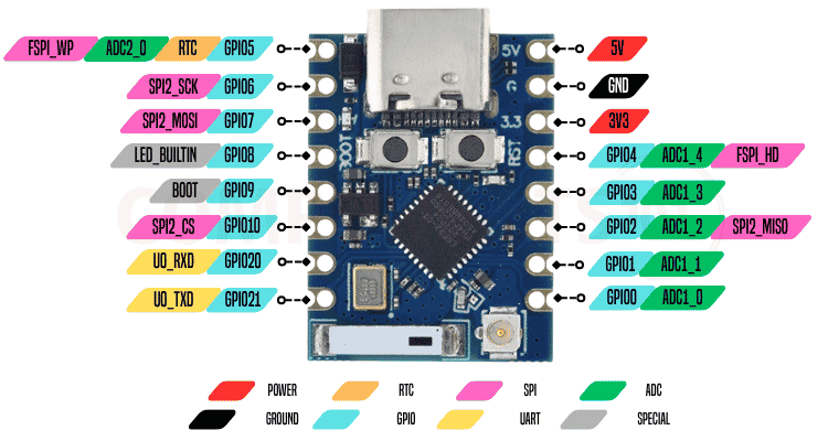
GPIO2 is another strapping pin used during the boot process and should ideally be avoided for general-purpose use whenever possible. External circuitry that changes its level during reset or power-up can affect the selected boot configuration and potentially cause unexpected startup behaviour. If GPIO2 must be used, ensure that the connected hardware does not force an incompatible logic level during boot.
Pin Configuration Table
| Pin Label | GPIO Number | Primary / Alternate Functions | Description |
| 5V | - | Power Input (5V) | External 5V power input or 5V output when powered via USB-C. |
| G | - | Power Ground (GND) | Common ground reference. |
| 3.3 | - | Power Output / Input (3V3) | Regulated 3.3V power output (from onboard LDO) or direct 3.3V input. |
| 4 | GPIO04 | ADC1_CH4, FSPI_HD | General-purpose I/O, 12-bit Analog Input (ADC1 Channel 4), SPI HD. |
| 3 | GPIO03 | ADC1_CH3 | General-purpose I/O, 12-bit Analog Input (ADC1 Channel 3). |
| 2 | GPIO02 | ADC1_CH2, SPI2_MISO, Strapping | General-purpose I/O, Analog Input (ADC1 Channel 2), SPI MISO. Strapping pin. |
| 1 | GPIO01 | ADC1_CH1 | General-purpose I/O, 12-bit Analog Input (ADC1 Channel 1). |
| 0 | GPIO00 |
ADC1_CH0, RTC_GPIO0 |
General-purpose I/O, 12-bit Analog Input (ADC1 Channel 0), RTC wakeup. |
| 5 |
GPIO05 |
ADC2_CH0, FSPI_WP, RTC_GPIO5 |
General-purpose I/O, 12-bit Analog Input (ADC2 Channel 0), SPI WP. |
| 6 |
GPIO06 |
SPI2_SCK, FSPICLK | General-purpose I/O, SPI Clock line. |
| 7 | GPIO07 |
SPI2_MOSI, FSPID |
General-purpose I/O, SPI MOSI data line. |
| 8 | GPIO08 | LED_BUILTIN, Strapping |
Connected to onboard blue/green User LED (Active LOW). Strapping pin. |
| 9 | GPIO09 |
BOOT Button, Strapping |
Connected to onboard BOOT tactile switch (Active LOW). Strapping pin. |
| 10 | GPIO10 |
SPI2_CS, FSPICS0 |
General-purpose I/O, SPI Chip Select line. |
| 20 |
GPIO20 |
U0_RXD |
Hardware UART0 Receive (RX) pin. |
| 21 | GPIO21 | U0_TXD |
Hardware UART0 Transmit (TX) pin. |
Market Names & Official Espressif Modules
When searching online marketplaces, you may encounter this board under various names, including ESP32-C3 Super Mini, ESP32-C3 Mini, ESP32-C3 Pro Mini, ESP32-C3 Mini Development Board, and HW-466 / HW-466AB. Despite these different naming conventions, all of these boards are built around the same underlying Espressif ESP32-C3 SoC. The differences primarily concern third-party board design, PCB colour (black or blue), and antenna configuration. Therefore, these names do not indicate different silicon revisions or separate processor families.
Official Espressif Modules vs. Third-Party Breakout Boards
To avoid confusion, it is essential to distinguish between Espressif’s official surface-mount modules and third-party development boards:
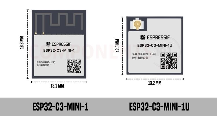
The ESP32-C3-MINI-1 and ESP32-C3-MINI-1U are Espressif’s official surface-mount modules. The ESP32-C3-MINI-1 features an integrated PCB trace antenna and measures 16.6 mm × 13.2 mm, while the ESP32-C3-MINI-1U features an external U.FL/IPEX antenna connector and measures 12.5 mm × 13.2 mm.
Third-Party Breakout Boards:
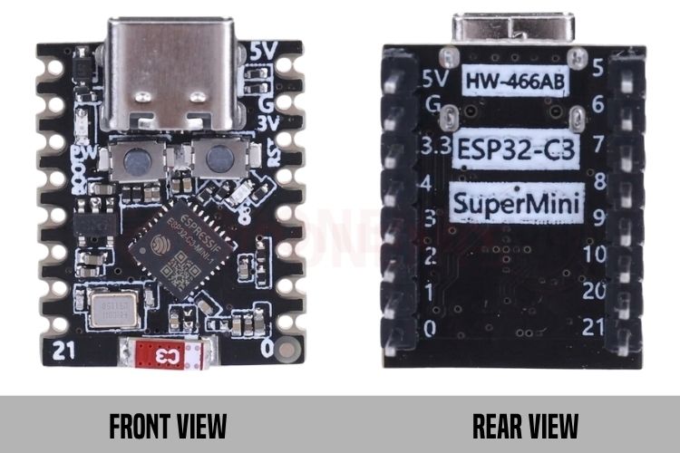
In contrast, boards marketed as the ESP32-C3 Super Mini or ESP32-C3 Pro Mini are third-party development boards that integrate an ESP32-C3 chip with supporting hardware. These boards typically include an onboard 3.3V LDO regulator, USB-C port, BOOT and RESET buttons, power/user LEDs, and standard 2.54 mm pin headers, with variations in board layout, antenna configuration, and other hardware depending on the manufacturer.
Super Mini vs. Pro Mini vs. Official Modules
While all versions share the ESP32-C3 core, choosing the right board variant depends heavily on your application's physical space and RF range requirements.
|
Feature |
ESP32-C3 Super Mini |
ESP32-C3 Pro Mini |
ESP32-C3-MINI-1 |
ESP32-C3-MINI-1U |
| Antenna Type |
Ceramic Chip Antenna |
Ceramic Chip + IPEX / U.FL |
On-module PCB Trace |
External U.FL / IPEX |
| IPEX Connector | No | Yes (Selectable via jumper) | No | Yes (Dedicated) |
| USB & Buttons |
USB-C, BOOT, RESET |
USB-C, BOOT, RESET |
None (Requires carrier) | None (Requires carrier) |
| Wi-Fi Range |
Short (~3-8 meters) |
Long (30-50m+ with ext. antenna) |
Medium (~15-30 meters) |
Long (30-50m+ with ext. antenna) |
| Best For |
Ultra-compact wearables & beacons |
Long-range IoT sensors & metal enclosures |
Custom commercial PCB designs |
Custom commercial long-range IoT |
RF Performance & Antenna Switching (Ceramic vs. IPEX)
One of the most important considerations with the ESP32-C3 Super Mini is its relatively limited Wi-Fi and Bluetooth range. Due to its extremely compact PCB layout, the small ceramic chip antenna is positioned close to ground traces and the crystal oscillator, leaving limited RF clearance around the antenna. This can reduce antenna efficiency and result in greater signal attenuation, particularly when the signal must pass through walls or other obstacles.
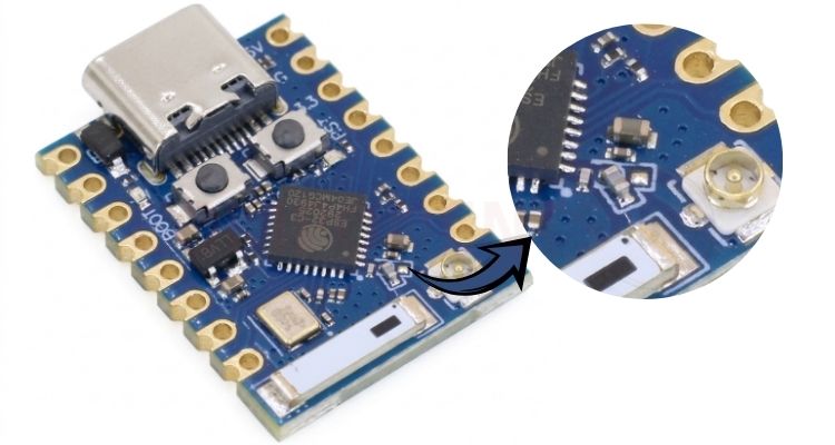
For applications requiring improved wireless range, such as long-range IoT nodes, outdoor sensors, or projects installed inside enclosures, the ESP32-C3 Pro Mini is generally a better choice. It provides both an onboard ceramic antenna and a miniature U.FL/IPEX connector, allowing an external antenna to be used when required.
Comparison Between ESP32-C3 vs ESP32-S3 Families and Development Boards
The ESP32-C3 and ESP32-S3 are both highly capable Wi-Fi and Bluetooth SoCs, but they target different levels of performance and application requirements. The ESP32-C3 uses a single-core 32-bit RISC-V processor and is designed for cost-effective, low-power IoT applications.
The ESP32-S3 uses a dual-core Xtensa LX7 processor, offers more processing capability, larger memory options, and features such as vector instructions that make it better suited for AI/ML, audio, image processing, and more demanding embedded applications.
The choice becomes particularly interesting when comparing boards such as the ESP32-C3 Super Mini and XIAO ESP32-S3 with Espressif's official C3-MINI, S3-MINI, and S3-WROOM modules.
| Feature | ESP32-C3 Super Mini | XIAO ESP32-S3 | ESP32-C3-MINI-1 | ESP32-C3-MINI-1U | ESP32-S3-MINI-1 | ESP32-S3-MINI-1U | ESP32-S3-WROOM-1 |
| Type |
3rd-party development board |
Development board | Official module | Official module | Official module | Official module | Official module |
| SoC |
ESP32-C3 |
ESP32-S3 |
ESP32-C3 |
ESP32-C3 |
ESP32-C3 |
ESP32-C3 |
ESP32-C3 |
| CPU | 1× RISC-V |
2× Xtensa LX7 |
1× RISC-V |
1× RISC-V |
2× Xtensa LX7 |
2× Xtensa LX7 |
2× Xtensa LX7 |
| Max. Frequency |
160 MHz |
240 MHz | 160 MHz | 160 MHz | 240 MHz | 240 MHz | 240 MHz |
| SRAM | 400 KB |
512 KB |
400 KB | 400 KB |
512 KB |
512 KB | 512 KB |
| PSRAM | Usually none | 8 MB | None |
None |
None/2MB |
None/2MB |
None/2MB/8MB |
| Flash |
Typically 4 MB |
8 MB |
4/8 MB* | 4 MB | 4/8 MB* |
4/8 MB* |
4/8/16 MB* |
| Wi-Fi |
2.4 GHz 802.11 b/g/n |
2.4 GHz 802.11 b/g/n |
2.4 GHz 802.11 b/g/n |
2.4 GHz 802.11 b/g/n | 2.4 GHz 802.11 b/g/n | 2.4 GHz 802.11 b/g/n |
2.4 GHz 802.11 b/g/n |
| Bluetooth | BLE 5 |
BLE 5 |
BLE 5 |
BLE 5 | BLE 5 | BLE 5 | BLE 5 |
| GPIOs |
Board-dependent |
11 exposed |
Up to 15 |
Up to 15 |
Up to 39 | Up to 39 | Up to 41 |
| USB |
USB-C / USB Serial-JTAG |
USB-C / USB OTG |
USB Serial-JTAG |
USB Serial-JTAG |
USB 2.0 OTG + Serial/JTAG |
USB 2.0 OTG + Serial/JTAG |
USB 2.0 OTG + Serial/JTAG |
| Antenna | Usually PCB | PCB | PCB | External | PCB | External | PCB |
| Module Size | ~22.5 × 18 mm board | 21 × 17.8 mm board | ~13.2 × 16.6 mm | ~13.2 × 12.5 mm | 15.4 × 20.5 mm |
15.4 × 15.4 mm |
18 × 25.5 mm |
| AI / Vector Support | No | Yes | No |
No |
Yes |
Yes |
Yes |
| Camera / Display Interfaces | Limited | Yes | Limited | Limited |
Yes |
Yes |
Yes |