MEAN WELL Peripheral Accessories are designed to fulfill customers' one-stop shopping requirements.
Transistors: Differences between NPN and PNP Transistors
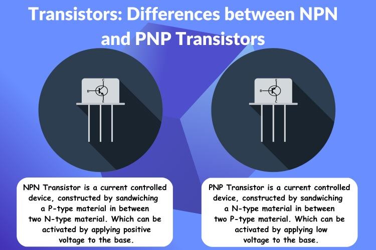
Transistors are the most important invention in the field of electronics. The invention of the transistor revolutionized the electronics industry. The transistor is a three-terminal current control device, that can be used to create complex electronic circuits. Even though there are other types of transistors, Bipolar Junction Transistors (BJT) are still popular and used everywhere. So, we will discuss about BJTs and the difference between NPN and PNP transistors.
PNP and NPN Transistor Working
The basic principles of operation of both NPN and PNP transistors are the same. The only difference is in their basing and the power supply polarity for each type. In the NPN transistor the current flows between the collector and the emitter when a positive supply is given to the base. But in the PNP transistor the current flows from emitter to collector when the base is supplied with a negative supply.
In an NPN transistor, a positive voltage applied to the base relative to the emitter forward biases the base-emitter junction, allowing current to flow from the emitter to the collector. This current amplification is governed by the base current, with the collector current significantly larger than the base current. In the animation below, you can see that, when the base of an NPN transistor is pulled high, it will turn on and start conducting, thus turning on the LED. When its base is pulled low the transistor turns off.
Conversely, in a PNP transistor, a negative voltage applied to the base relative to the emitter reverse biases the base-emitter junction, enabling current flow from the emitter to the collector. Again, amplification occurs, controlled by the base current. When the base-emitter junction is reverse biased in an NPN transistor or forward biased in a PNP transistor, the transistor is in the off state, halting significant collector current flow. That is when the base is pulled high it turns itself off and when it’s pulled low it turns itself on.
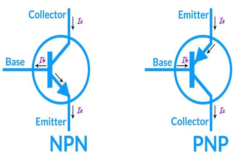
The image below shows the current flow in each type of transistor. You can see that the current in the NPN is flowing from collector to emitter while in the PNP the current flows from emitter to collector.
PNP and NPN Transistor Construction
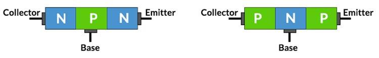
As the name indicates an NPN transistor is constructed by sandwiching a P-type material in between two N-type materials, whereas in a PNP transistor, an N-type material is sandwiched in between two P-type materials. In an NPN transistor electrons are the majority charge carriers, whereas in a PNP the majority charge carriers are the holes, because of this the NPS transistors have faster recovery time when compared to the PNP type. It leads to the NPN having a very small switch ON and Switch OFF time, therefore offering a very high switching speed. The image below demonstrates the typical structure of both NPN and PNP transistors.
PNP and NPN Transistor Symbol
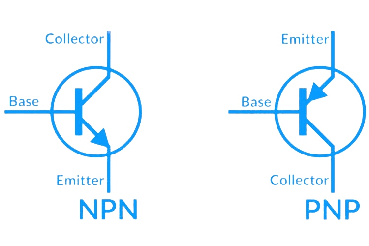
The NPN transistor symbol typically features an arrow pointing outward from the base terminal, indicating the direction of conventional current flow. The emitter is denoted by a diagonal line with an arrowhead, while the collector is represented by a straight line opposite the emitter. A third line entering at a right angle between the emitter and collector signifies the base. In contrast, the PNP transistor symbol resembles the NPN symbol but with the arrow pointing inward towards the base, representing the opposite direction of conventional current flow.
How to Identify NPN and PNP Transistors
When you're unsure about the pinout of a transistor, identifying whether it's an NPN or PNP transistor using a multimeter becomes a bit more challenging but still feasible. Here's a method:
Start by setting your multimeter to the diode test mode (or continuity mode). Place the red probe on one of the transistor's terminals and the black probe on another terminal. Keep the third terminal unconnected for now. With the probes connected to two terminals, observe the multimeter's reading. If you get a voltage, drop or hear a beep, it indicates a forward-biased junction between the two terminals. Now disconnect the black probe and connect it to the previously unconnected terminal. If you get a voltage, drop with this configuration, you can confirm that it is an NPN transistor. If you don’t get a voltage, drop, connect the black probe back to the first terminal and connect the red probe to the unconnected terminal. If you get a voltage, drop in this configuration you can confirm it is a PNP transistor.
If you don’t get a reading at the first step, then interchange the probes and continue as already mentioned. In single terms for an NPN transistor, the meter should give a voltage drop with a red probe connected to the same terminal and the black probe to either one of the other pins. For PNP it should be with a black probe to one terminal and red to either of the other terminals. Keep in mind that is test is to be used with a digital multimeter. For analog-type multimeters, the probe polarity will be different.
How to Test NPN and PNP Transistors
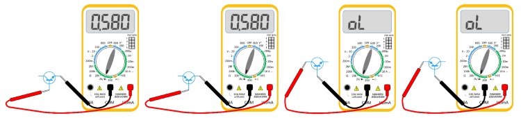
To test NPN and PNP transistors using a multimeter, you'll need to follow a systematic approach. Let's start with the NPN transistor. Begin by setting your multimeter to the diode test mode. First, place the red probe on the base (B) of the transistor and the black probe on the emitter (E). If the multimeter displays a voltage drop, typically around 0.6 to 0.7 volts, it indicates that the base-emitter junction is forward-biased, suggesting that it's an NPN transistor. Next, switch the black probe to the collector (C), maintaining the red probe on the base. If there's no significant change in the reading, it confirms the proper functioning of the transistor.
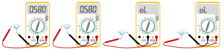
Now, for the PNP transistor test, keep the multimeter in diode test mode. Start by placing the black probe on the base (B) and the red probe on the emitter (E). If you observe a voltage, drop, usually around 0.6 to 0.7 volts, it signifies a forward-biased base-emitter junction, indicating it's a PNP transistor. Afterwards, move the red probe to the collector (C), while keeping the black probe on the base. If the reading remains consistent, it confirms that the transistor is working as expected.
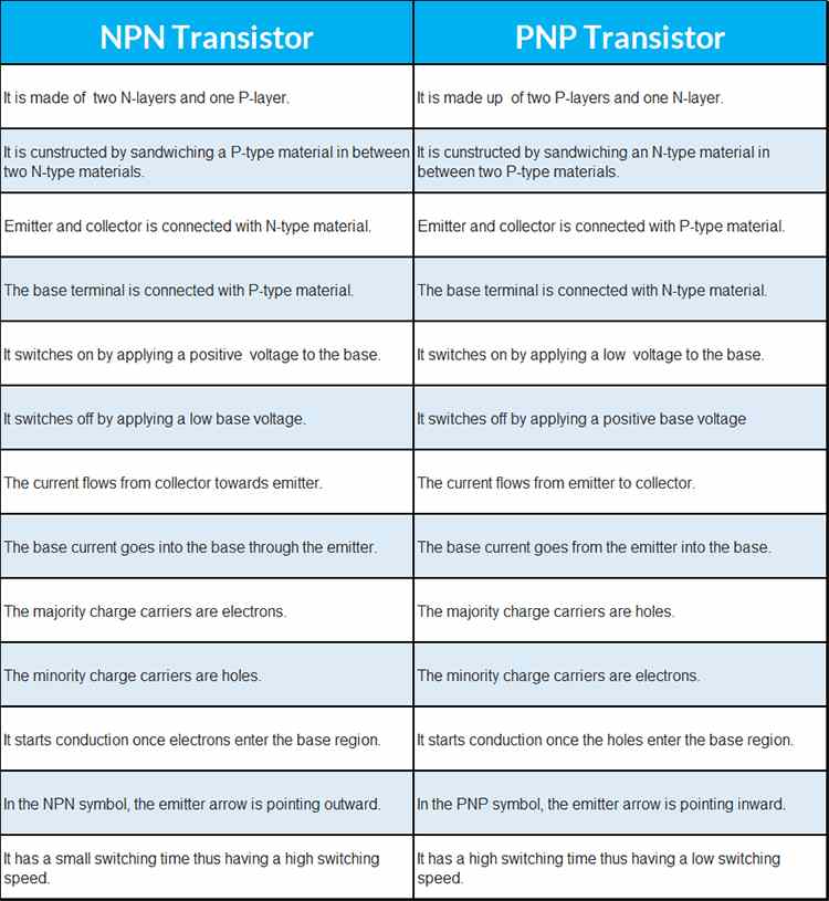
Differences Between NPN vs PNP
Here are the key differences between NPN and PNP transistors as a table.
Why NPN Transistors are more popular than PNP Transistors
The preference for either an NPN or PNP transistor depends on the specific needs and context of the application. Both types offer distinct advantages and find utility in various scenarios. Below are several reasons why NPN transistors are favored in certain circumstances:
- Common Ground Reference: NPN transistors are often preferred in circuits where a common ground reference is used. This is because the collector current flows into the NPN transistor through the load and then to the ground. This common ground reference simplifies circuit design and can be advantageous in many applications.
- Higher Electron Mobility: In NPN transistors, electrons are the majority charge carriers. Electrons have higher mobility than holes (the majority charge carriers in PNP transistors), which means NPN transistors tend to have better overall performance characteristics, such as higher current gain and faster switching speeds.
- Compatibility with N-Channel MOSFETs: NPN transistors are often used in conjunction with N-channel MOSFETs in digital and analog circuit designs. This combination allows for easy interfacing between low-power control signals (coming from NPN transistors) and high-power devices (controlled by N-channel MOSFETs).
- Availability: NPN transistors are more commonly available and widely used than PNP transistors. This availability makes them a preferred choice in many situations due to lower cost and ease of sourcing.
- Complementary Pairing: In push-pull amplifier configurations, NPN transistors can be conveniently paired with PNP transistors to achieve a complementary push-pull output stage, which is commonly used in audio amplifiers.
- Simplified Logic Levels: In digital electronics, NPN transistors can be used to interface with logic circuits because they are often used for low side switching (ground switching). This can simplify the control logic in some cases.
Popular NPN and PNP Transistors
Some popular NPN transistors include:
- 2N2222: Widely used for general-purpose switching and amplification applications.
- BC547: Commonly employed in low-level amplification and switching circuits.
- BC337: Suitable for medium power amplification and switching applications.
- PN2222A: Similar to 2N2222, often used in various electronic projects.
- 2N3904: Another versatile transistor used in a wide range of applications.
- 2N3055: Power NPN transistor capable of handling higher currents, commonly used in power supply and audio amplifier circuits.
As for PNP transistors, some popular ones are:
- 2N2907: Frequently utilized for amplification and switching purposes.
- BC557: Comparable to BC547 but with PNP configuration, commonly found in low-power applications.
- BC327: Suitable for medium-power amplification and switching circuits. BC558: Similar to BC548 but with PNP configuration, commonly used in low-level applications.
- 2N3906: Complementary to 2N3904, often used in low-power amplification and switching circuits.