MCP23017 16-Bit I2C I/O Expander
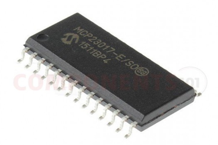
The MCP23017 is a widely used 16-bit I/O expander manufactured by Microchip Technology. It facilitates parallel input/output expansion for microcontrollers via the I2C serial interface. This integrated circuit (IC) offers 16 GPIO (General Purpose Input/Output) pins, which can be configured individually as inputs or outputs. Its bi-directional capability allows for flexibility in interfacing with various peripherals and sensors. The MCP23017 operates within a wide voltage range, typically from 1.8V to 5.5V, making it compatible with a broad range of microcontroller systems. Additionally, it features programmable pull-up resistors on each GPIO pin, enhancing signal integrity. With its straightforward interfacing and extensive configurability, the MCP23017 serves as a versatile solution for expanding I/O capabilities in embedded systems and microcontroller-based projects.
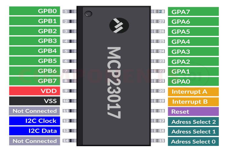
MCP23017 Pinout Configuration
Here are the pinout details for the MCP23017 I/O expander IC. As you know the MCP23017 has 28 pins, and in which 16 can be used as bidirectional IOs. The table below shows the function of each pin. Please note that the QFN package has a different pin configuration than the other package, and it has been highlighted in the table below.
| PACKAGE | ||||
| Pin Name | SOIC SPDIP SSOP | QFN | Pin Type | Function |
| GPB0 | 1 | 25 | I/O | Bidirectional I/O |
| GPB1 | 2 | 26 | I/O | Bidirectional I/O |
| GPB2 | 3 | 27 | I/O | Bidirectional I/O |
| GPB3 | 4 | 28 | I/O | Bidirectional I/O |
| GPB4 | 5 | 1 | I/O | Bidirectional I/O |
| GPB5 | 6 | 2 | I/O | Bidirectional I/O |
| GPB6 | 7 | 3 | I/O | Bidirectional I/O |
| GPB7 | 8 | 4 | I/O | Bidirectional I/O |
| VDD | 9 | 5 | P | Power |
| VSS | 10 | 6 | P | Ground |
| NC/CS | 11 | 7 | I | NC |
| SCK | 12 | 8 | I | I2C Clock |
| SDA/SI | 13 | 9 | I/O | I2C DATA |
| NC/SO | 14 | 10 | O | NC |
| A0 | 15 | 11 | I | Address select pin |
| A1 | 16 | 12 | I | Address select pin |
| A2 | 17 | 13 | I | Address select pin |
| RESET | 18 | 14 | I | Hardware reset |
| INTB | 19 | 15 | O | Interrupt output for PORTB |
| INTA | 20 | 16 | O | Interrupt output for PORTB |
| GPA0 | 21 | 17 | I/O | Bidirectional I/O |
| GPA1 | 22 | 18 | I/O | Bidirectional I/O |
| GPA2 | 23 | 19 | I/O | Bidirectional I/O |
| GPA3 | 24 | 20 | I/O | Bidirectional I/O |
| GPA4 | 25 | 21 | I/O | Bidirectional I/O |
| GPA5 | 26 | 22 | I/O | Bidirectional I/O |
| GPA6 | 27 | 23 | I/O | Bidirectional I/O |
| GPA7 | 28 | 24 | I/O | Bidirectional I/O |
Features
● 16-bit I/O expander IC
● Interfaces with microcontrollers via I2C serial interface.
● High-Speed I2C Interface. Supports 100 kHz, 400 kHz and 1.7 MHz.
● Provides 16 GPIO pins
● Individual pin configuration as input or output.
● Bi-directional capability
● Wide voltage range: typically 1.8V to 5.5V
● Programmable pull-up resistors on each GPIO pin
● Three Hardware Address Pins to Allow Up to Eight Devices On the Bus.
● Low Standby Current: 1 µA (max.)
● Configurable Interrupt Output Pins.
● Suitable for expanding I/O capabilities in embedded systems and microcontroller-based projects.
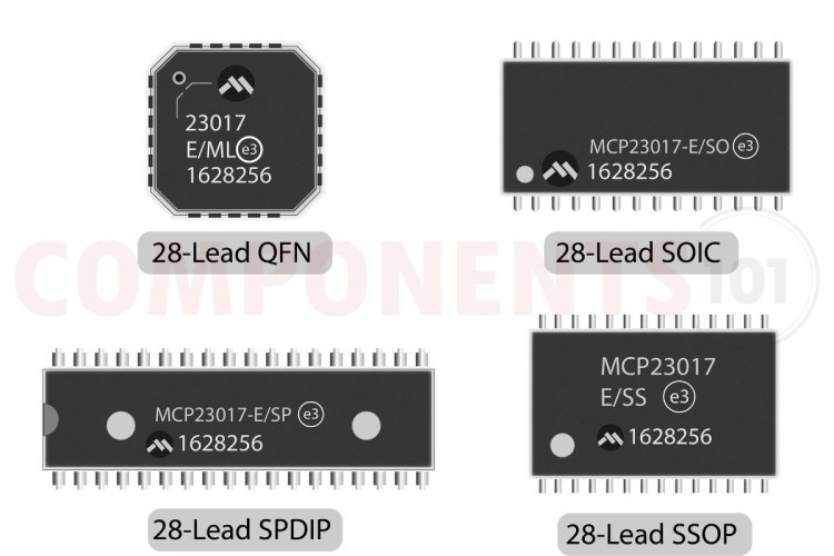
MCP23017 Available Packages
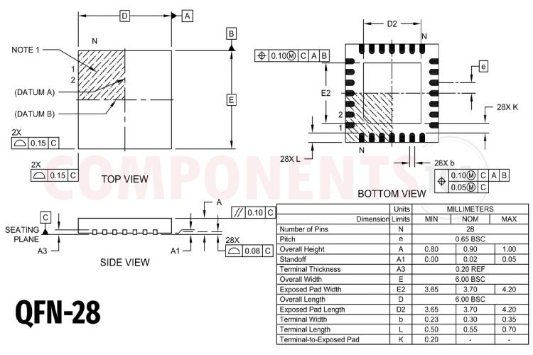
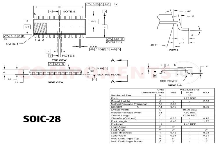
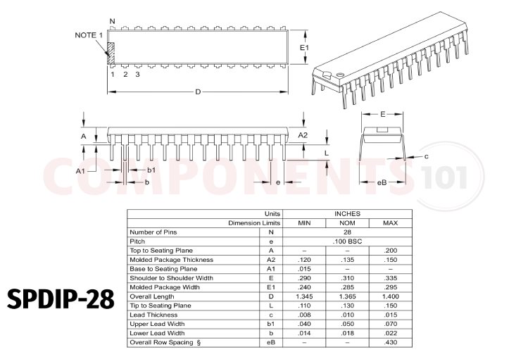
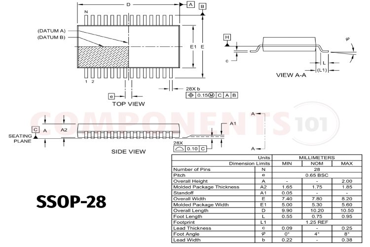
The MCP23017 is available in 4 different pancakes, QFN-28, SOIC-28, SPDIP-28 and SSOP-28.
Manufacturers of MCP23017:
The MCP23017 is manufactured by Microchip Technology. There are no alternative manufacturers for the same part number as of the date of writing this article.
MCP23017 Equivalents
There aren't any pin-to-pin compatible equivalents available for MCP23017. You may check out MCP23S17, which has almost the same pinout but uses SPI instead of I2C for communication. So the functions of some pins are different than the MCP23017, But the packages and I/O pin arrangement are the same.
MCP23017 Alternatives
PCA9538, PCF8574, SX1509, MAX7313, STMPE610
Note: Complete technical details can be found in the MCP23017 datasheet at this page’s end.
MCP23017 Schematics
The following image shows the typical MCP23017 circuit diagram.
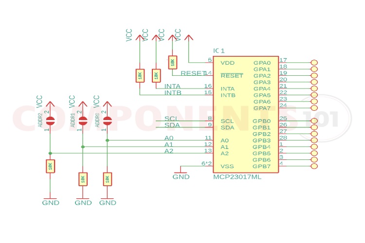
As you can see the circuit is very simple and only requires bare minimum components. We have added external pull-up and pull-down resistors to the interrupt, reset and address select pins. You can change the I2C address of the device using the jumpers provided in the schematics. Different combinations of these jumpers will assign different I2C addresses.
MCP23017 Arduino Interfacing
Interfacing the MCP23017 with Arduino involves connecting the MCP23017 to the Arduino board and using a library to communicate with it via the I2C bus. Here's a basic guide to get started:
Connect the MCP23017 to the Arduino using the I2C bus. The MCP23017 has two I2C addresses, allowing you to connect multiple MCP23017s to the same I2C bus. Connect the SDA pin of the MCP23017 to the SDA pin on the Arduino, and connect the SCL pin of the MCP23017 to the SCL pin on the Arduino. Also, connect VCC and GND pins to power and ground respectively.
Install the MCP23017 Arduino library by ndomx from the library manager. In your Arduino sketch, include the MCP23017 library and create an instance of the MCP23017 object. Configure the MCP23017 pins as inputs or outputs using the pinMode() function provided by the library. You can set individual pins as inputs or outputs according to your project requirements. Read inputs from the MCP23017 using the digitalRead() function or write outputs using the digitalWrite() function provided by the library. These functions allow you to interact with the GPIO pins of the MCP23017 as if they were directly connected to the Arduino.
Here's a simplified example code snippet demonstrating basic usage.
// Blink a LED
#include <mcp23017.h>
#define MCP_ADDR (0)
MCP23017 mcp(MCP_ADDR);
void setup(void)
{
    mcp.start();
    mcp.pinMode(GPB7, OUTPUT);
}
void loop(void)
{
    mcp.digitalWrite(GPB7, HIGH);
    delay(250);
    mcp.digitalWrite(GPB7, LOW);
    delay(250);
}
This code initializes the MCP23017, sets pin GPB7 as output, and alternates between turning it on and off with a delay of 250 milliseconds. Adjust the code according to your specific requirements and pin configurations.
Design Tips forMCP23017
What is the use of MCP23017?
The MCP23017 is used to expand the number of input/output pins on microcontrollers, enabling them to interface with more external devices and simplifying circuit design.
How does the MCP23017 work?
It communicates with microcontrollers through the I2C bus, extending the number of available GPIO pins that can be configured as inputs or outputs.
What are the key features of the MCP23017?
It offers 16 GPIO pins, individual pin configuration, bi-directional capability, wide voltage range (1.8V to 5.5V), programmable pull-up resistors, and multiple address options for connecting multiple devices.
How do I interface the MCP23017 with Arduino?
Connect the MCP23017 to the Arduino using the I2C bus and utilize the appropriate library to communicate with it. Initialize the object, configure pins, and read/write data as needed.
Can I use multiple MCP23017s in the same project?
Yes, the MCP23017 supports multiple devices on the same I2C bus, each with a unique address, allowing for the expansion of I/O capabilities by using multiple MCP23017 chips.
Does the MCP23017 support interrupt handling?
Yes, it supports interrupt capability, allowing microcontrollers to respond quickly to changes in input states without continuously polling the device.
Troubleshooting Tips for MCP23017
Troubleshooting issues with the MCP23017 can be facilitated by considering several common factors. Here are some troubleshooting tips:
- Ensure that all connections between the MCP23017 and the microcontroller (e.g., Arduino) are secure and correctly wired according to the datasheet and your schematic. Verify the connections for power (VCC and GND), I2C communication lines (SDA and SCL), and any additional pins used for interrupt handling or other features.
- Confirm that the MCP23017 is receiving the correct voltage supply within its specified operating range (typically 1.8V to 5.5V). Check the power supply connections and measure the voltage to ensure it meets the requirements of the MCP23017.
- Verify that the I2C communication between the microcontroller and the MCP23017 is functioning correctly. Use an I2C scanner sketch on the microcontroller to detect the MCP23017's address and ensure it is accessible on the bus. If the MCP23017 is not detected, check the wiring and address configuration.
- If using multiple MCP23017 chips on the same I2C bus, ensure that each chip has a unique address set using the A0, A1, and A2 address pins. Double-check the address configuration and verify that there are no conflicts between devices sharing the bus.
- Make sure that you are using the correct library for interfacing with the MCP23017 and that it is properly installed in your Arduino IDE. Review your code for any errors, ensure that the MCP23017 object is initialized correctly with the correct address, and verify that pin configurations and I/O operations are performed accurately.
- If using the MCP23017's internal pull-up resistors, verify that they are enabled in your code if needed. Alternatively, if external pull-up resistors are used, ensure they are connected correctly and have the appropriate resistance value.
- Test the functionality of individual GPIO pins by configuring them as inputs and outputs and verifying their behavior using simple test sketches. This can help identify potential issues with specific pins or circuits connected to them.
- Inspect the MCP23017 and surrounding components for any signs of physical damage, such as burnt components, solder bridges, or loose connections. Replace any damaged components and reflow solder joints if necessary.
Applications
- Embedded Systems
- Home Automation
- Industrial Automation
- Robotics
- Instrumentation
- LED Matrix Displays
- Keypad and Button Interfaces
- IoT (Internet of Things) Devices
2D-Model and Dimensions
Below is the 2D CAD drawing of MCP23017 along with its dimensions. The dimensions can be used to create custom footprints of the module and be used for PCB or CAD modeling. We have also included 2D CAD drawings for other packages that MCP23017 is available.