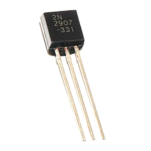
2N2907 Bipolar PNP Transistor
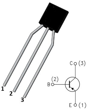
2N2907 Pin Configuration
|
Pin No. |
Pin Name |
Description |
|
1 |
Emitter |
Current Drains out through emitter |
|
2 |
Base |
Controls the biasing of transistor |
|
3 |
Collector |
Current flows in through collector |
Features and Technical Specification
- Having a high value of current (max. 600 mA)
- Low voltage value (max. 40 V)
- Comes in different type of packages – TO-92, TO-18
- These are Lead (Pb) free devices
- Collector to Emitter voltage (VCEO) is 40v (max.)
- Collector to Base voltage (VCBO) is 60v (max.)
- Emitter to Base voltage(VEBO) is 5v (normally)
- Maximum value of Collector current is 600mA
- Power dissipation at ambient temperature is about 400mW
- Having DC current gain (hfe) of 100 to 300 (max.)
- Temperature of operation and storage is -65 to +150 °C
Note: Complete technical information can be found in the 2N2907 Datasheet, linked at the bottom of this page.
2N2907 Equivalent Transistors
2N2907A, NTE159M
Brief Description
This is a Bipolar PNP transistor available in metal can package, having a high value of current 600mA with low voltage of 40v. The condition of being forward biased is when the base connected to the ground or having no supply on it, and as a signal is provided to base pin it goes reverse biased. The transistor is having DC current gain value of 100 to 300 which shows the amplification capacity of the transistor. As it is used for the amplification and switching.
When the transistor is fully biased, it allows a maximum of 500mA current through the collector and provide a voltage (collector to emitter) of 1.6v (max.), this is the Saturation region of the transistor. While the base current is removed the transistor is in off state it’s in Cut-off region.
2N2907 Transistor as Switch
When use as a switch, can be operated in saturation region and cut-off region. In PNP transistor, by default it’s in ON state, but not to be said perfectly on until the base pin is not grounded. If we provide ground to the base pin, then the transistor will be in reverse biased and said to be turn ON. If supply is provided to the base pin, it stops conducting current between emitter and collector and said to be in OFF state. For the protection of transistor, a resistance added in series with it. For finding the value of that resistor, you can use the formula:
RB = VBE / IB
Where, the value of VBE will be 5v for this transistor. The maximum value of providing base current is 200mA. So, from that you can find the value of resistance to be added in series with it.
2N2907 Transistor as Amplifier
When use as a amplifier, can be operated in the active region. When its base is connected to ground, it will allow high current (600mA) to pass through collector to emitter, that’s how it amplifies the current. There are three configuration used in an amplifier circuit are common emitter, common base, common collector. This transistor is used where low power amplification is needed. It can also amplifies the power and current. Amplification factor usually determined in term of power; for calculating the current gain, we use the formula:
Gain (hfe) = IC / IB
Where, IC is the collector current and IB is the base current of the circuit.
Applications
- Where amplification of low power is needed we use this transistor.
- It can also be used in the various switching applications.
- Used for making siren or dual Led or Lamp flasher.
- Can be used in Darlington Pair.
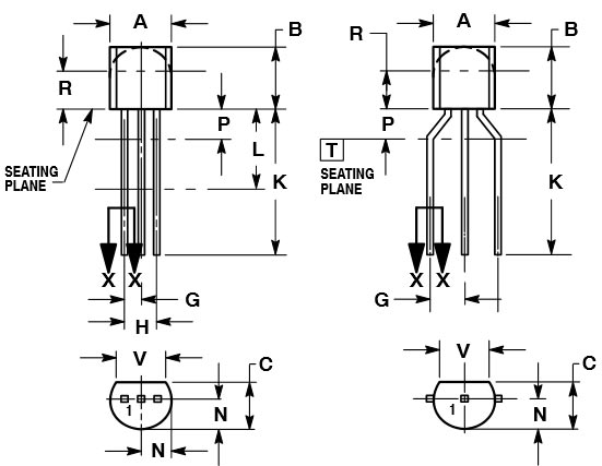
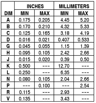
2D-Model and Dimensions
2D dimensions will help you in placing this component at the time of making circuit on perf board or a PCB.