TA6586 bi-directional DC Motor Driver


TA6586 is a cheap Bi bi-directional DC motor driver IC with a wide input voltage range. It has two inputs to control the direction of the motor. This motor driver IC offers anti-interference performance, small standby current and low output saturation pressure drop. We can control relays, and DC motors with this IC without using any other electronic components. It has an inbuilt diode, which will prevent the reverse inductive load current. This is suitable for controlling hobby projects and other motor-operated circuits. The TA6586 is available in an 8-pin DIP Lead-free package.
TA6586 Pinout Configuration
Here are the pinout details for TA6586.
| Pin No | Name | Function |
| 1 | BI | Backward input |
| 2 | FI | Forward input |
| 3 | GND | Ground |
| 4 | Vcc | Supply voltage |
| 5, 6 | FO | Forward output |
| 7, 8 | BO | Backward output |
Features of TA6586
TA6586 bi-directional DC motor Driver has the following key features:
- Low standby current: ≦2uA
- Wide supply voltage range 3.0V~14V
- Built-in Brake Function
- Thermal Shutdown protection
- Over Current Limit and Short Circuit Protect Function
- DIP8 lead -Free package.
Manufacturers of TA6586:
The TA6586 is manufactured by RZ (Wuxi Smart Microelectronics). There are no alternative manufacturers for the same part number as of the date of writing this article.
TA6586 Equivalents
If you are looking for an equivalent or replacement for TA6586, we weren’t able to find any other chip that is pin-to-pin compatible.
TA6586 Alternatives
If you are looking for an alternative for TA6586 you can look at the other ICs from these.
L293D, L298, TB6612FNG, DRV8833, MAX1508, DRV8837, MAX1919, L9110, DRV8871
Note: Complete technical details can be found in the TA6586 datasheet at this page’s end.
TA6586 Schematics
The following image shows the typical circuit diagram for TA6586.
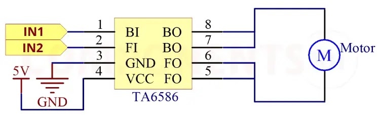
The above circuit diagram shows how to connect and drive a motor using TA6586. In this circuit, the motor is connected to pin BO and pin FO. You can connect the motor to the other BO and FO pins also. The ground pin is connected to to ground of the circuit. VCC is connected to a 5V power supply. To control the direction of the motor in the circuit we have connected the input pins to the output pins of a microcontroller. We can use any microcontroller here. You can control the motor according to this truth table.
| 2pin Finput | 1pin Binput | 5,6pin Foutput | 7,8pin Boutput |
| H | L | H | L |
| L | H | L | H |
| H | H | L | L |
| L | L | Open | Open |
Having Trouble with TA6586?
Why is my circuit not working?
1. Check all connections, and make sure everything is connected properly.
2. Check the motor voltage and current. Make sure that the rating is in the range of IC rating
3. Should connect the ground of the motor power supply and the logic circuit is commonly connected
The IC gets very hot and automatically turns off :
- Overloading: The motor driver IC may be driving a motor that draws more current than the IC can handle. Check the datasheet for the maximum current rating of the motor.
- Voltage Spikes: If there are voltage spikes or transients in the motor circuit, it could cause the IC to overheat. Adding capacitors to suppress these spikes can help protect the IC.
- Poor Heat Dissipation: The IC may not be dissipating heat efficiently. Make sure the IC is operating below 100 degrees Celsius.
- The motor is jerking: make sure the voltage and current rating of the motor match with the IC maximum parameters. Add .1uf capacitor parallel to the motor pins to reduce the noise.
Design Choices to be Considered with TA6586:
How to add reverse polarity protection to the circuit?
To add reverse polarity protection to a circuit using the TA6586, you can use a diode in series with the input supply. When the input supply is connected with the correct polarity, the diode conducts and allows the voltage to pass through to the TA6586. If the input supply is connected with reverse polarity, the diode blocks the current, protecting the TA6586 from damage.
How to do TA6586 Arduino Interfacing?
For controlling the TA6586 you will need two GPIO pins. Connect the inputs of TA6586 to these pins, set them as output and by changing the state of these pins you can control the TA6586 and the motor connected to it. You can refer to the truth table given above.
How to minimize the jerking of motors?
Add .1uf capacitor parallel with motor connections to minimize jerking.
Is a heat sink necessary for the working of TA6586?
No. For most applications, the TA6586 can operate without a heat sink within its specified operating conditions.
What are the design considerations when designing a PCB using TA6586?
The width of the tracks must be selected according to the motor current.
Applications of TA6586
- Robotics
- Motorized Vehicles
- Home Automation
- Industrial Automation
- Camera Gimbal Control
- Solar Tracking System
- DIY Projects
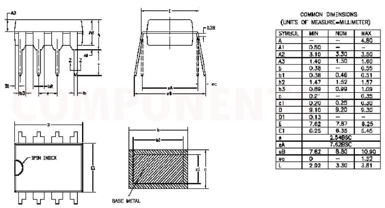
Footprint Dimensions for TA6586
Here you can find the mechanical drawings of TA6586 along with its dimensions. The dimensions can be used to create custom footprints of the module and be used for PCB or CAD modeling.