GT511C3 Fingerprint Scanner Module
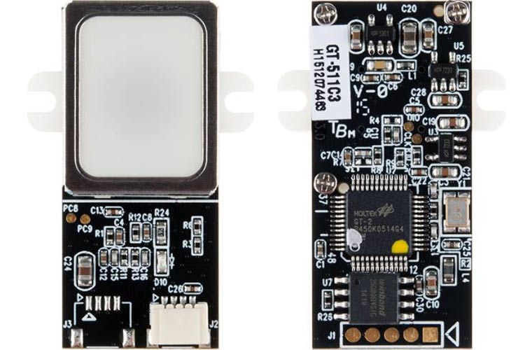
The GT-511C3 is a small embedded module that consists of an optical sensor mounted on a small circuit board. The optical sensor scans a fingerprint, and these scans are processed by ARM Microcontroller. This Module is useful for access control, security, identification, and convenience.
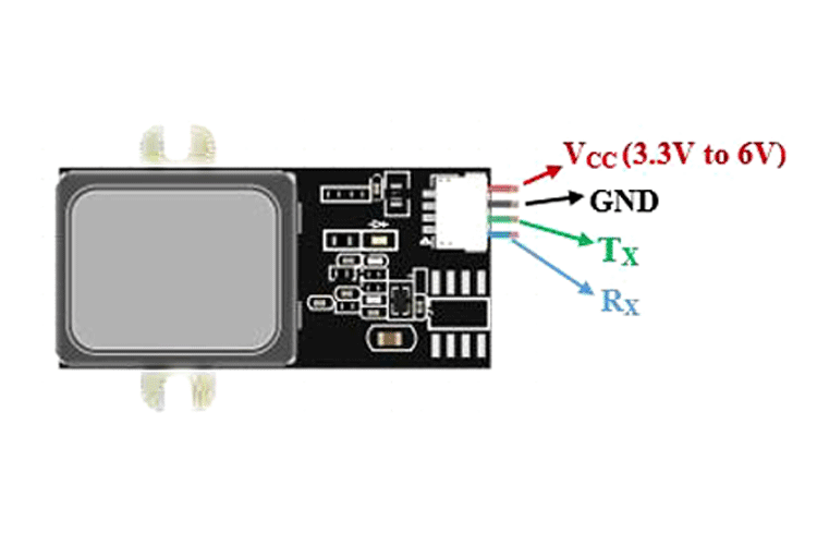
GT511C3 Module Pinout Configuration
|
Pin Name |
Description |
|
VCC |
The Vcc pin powers the Module, typically with +5V |
|
GND |
Power Supply Ground |
|
TX |
UART Transmitter Pin |
|
RX |
UART Receiver Pin |
GT511C3 Module Features & Specifications
- Operating Voltage: 3.3V to 6V DC
- Operating Current: < 130mA
- Operating Temperature: ~20°C ~ +60°C
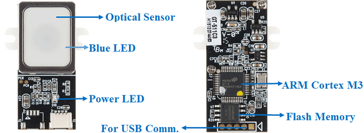
- CPU: ARM Cortex M3 Core (Holtek HT32F2755)
- Max no of fingerprints: 200 fingerprints
- Sensor: Optical Sensor
- Serial Communication: UART (Default: 9600 baud) and USB v1.1 (Full Speed)
- False Acceptance Rate (FAR): < 0.001%
- False Rejection Rate (FRR): < 0.01%
- Enrollment Time < 3 sec (3 fingerprints)
- Identification Time: <1.0 seconds (200 fingerprints)
Alternate Fingerprint Sensor Modules: GT-511C5, GT521F52, R305
Related Components: Optical Sensor, ARM Microcontroller, EEPROM
Brief about GT511C3 Module
GT511C3 Fingerprint Scanner module is very different from the Capacitive and Ultrasonic Fingerprint sensor modules. GT511C3 Module uses an optical sensor to scan fingerprints. These fingerprints are processed by powerful in-built ARM Cortex M3 IC. This scanner module can save up to 200 fingerprints scans, and it assigns an ID from 0 to 199 for each fingerprint.
This optical sensor module is designed for easy integration into applications with serial interface (UART). It has two wires for TX and RX and two wires for power supply.
The GT511C3 Module can also be directly interfaced to a computer through a USB connection. While using a USB connection, this Module can be controlled using the SDK_DEMO.exe application. This application allows you to enroll/verify/delete fingerprints.
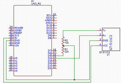
Interfacing with Arduino
Circuit diagram for interfacing GT511C3 with Arduino is given below. The GT511C3 is powered with 5V but the RX and TX pins are 3.3V tolerant, so we used a potential divider circuit with 10K and 22K resistors to convert 5V into 3.3V.
Applications of GT511C3 Module
- Access control
- Security
- Identification and convenience