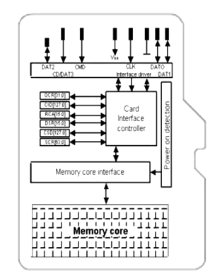
MicroSD Card
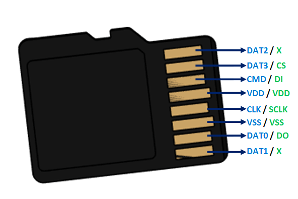
Pin Configuration
|
Pin Number |
Pin Name |
In SD Mode |
In SPI Mode |
|
1 |
DAT2/X |
Connector Data line 2 |
No use |
|
2 |
DAT3/CS |
Connector Data line 3 |
Chip Select |
|
3 |
CMD/DI |
Command / Response Line |
Data Input |
|
4 |
VDD/VDD |
Power supply (+3.3V) |
Power supply (+3.3V) |
|
5 |
CLK/SCLK |
Clock |
Serial Clock |
|
6 |
VSS/VSS |
Ground |
Ground |
|
7 |
DAT0/D0 |
Connector Data line 0 |
Data Out |
|
8 |
DAT1/X |
Connector Data line 1 |
No use |
MicroSD Card Features and Specifications
- Operating Voltage: 2.7V to 3.3V
- Capacity: 4GB, 8GB, 16GB, 32GB etc..
- File System: SD/SDHC/SDXC
- Storage System: FAT12 and FAT16
- Transfer Speed: 95 Megabytes per second (typically)
- Speed Class: Class 2 to Class 10
- Form Factor: 11mm × 15mm × 1mm
Where to use an SD card
SD Cards are the most commonly used Storage devices in embedded applications. Almost all microcontrollers have a limited Flash memory for programming and a limited EEPROM memory to store important data. However for projects involving Data logging or Pictures or other heavy graphics the programmer might have to save huge piece of data in terms of Mega bytes. In that situation an SD card is employed.
How to use an SD card
The terms SD card stands for “Secure Digital” Card, there are many types of SD cards starting from the RS-MMC big sized ones used in cameras to the micro and mini SD cards that are commonly used in mobile phones, MP3 players etc. Although there are few important differences between all these cards, the underlying working principle is all the same.
The SD cards can work in two operating modes, one is using the SD mode commands and the other is SPI mode. Most of the Digital cameras and mobile phones will use the SD mode to communicate with the SD card, however this is not of our interest because only the SPI mode to communicate between an SD card and a Microcontroller like Arduino (ATmel), PIC, AVR, etc.. A simple connection diagram for SPI with a microcontroller shown below:
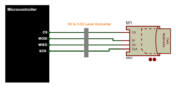
The SPI communication requires only four wires and is vastly supported by most of the microcontrollers. However the SD card operates with a voltage of 3.3V and all its pins speak with only 3.3V, the Microcontroller on the other hand might work with +5V in those cases a bi-directional logic level shifter (like 74HC245) that can convert the 5V signals to 3.3V is recommended. Once you have interfaced the Card you would have to initialize it and then start communicating with it through the SPI commands, it is not possible to cover the entire process here so you can read through the datasheet below to get more info.
Applications
- Portable Electronics
- Data Loggers
- Graphical Displays
- MP3 players
- Audio file handlers
- Image handlers
Architecture