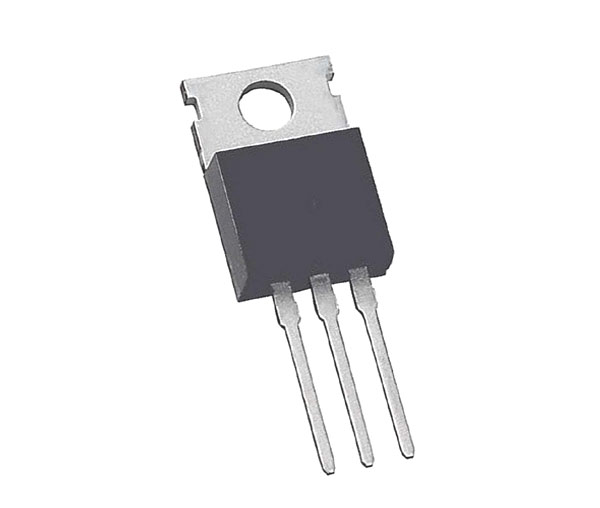
LM350T Adjustable Voltage Regulator
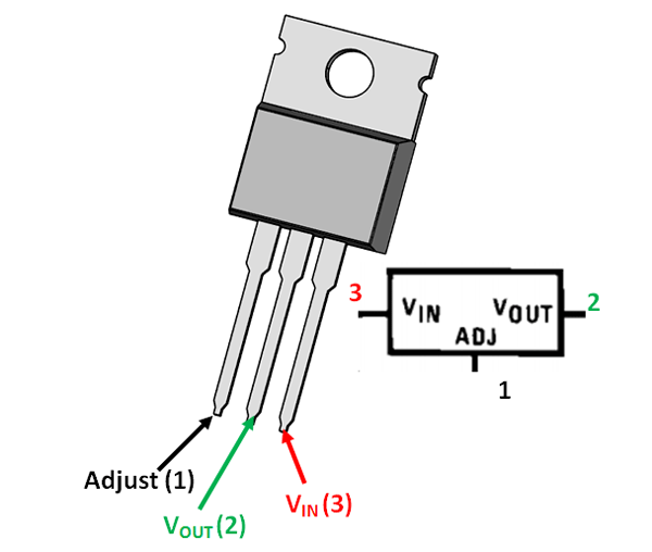
Pin Configuration
|
Pin Number |
Pin Name |
Description |
|
1 |
Adjust |
This pins adjusts the output voltage |
|
2 |
Output Voltage (Vout) |
The regulated output voltage set by the adjust pin can be obtained from this pin |
|
3 |
Input Voltage (Vin) |
The input voltage which has to be regulated is given to this pin |
Features
- Adjustable 3-terminal positive voltage regulator
- Output voltage can be set to range from 1.25V to 33V
- Maximum Output current is 3A
- Maximum Input to output voltage difference is 35V, recommended 15V
- Operating junction temperature is 125°C
- Available in To-220, SOT223, TO263 Package
Alternative Voltage Regulators
LM7805, LM7806, LM7809, LM7812, LM7905, LM7912, LM117V33, XC6206P332MR.
LM350 Equivalent Voltage Regulators
LM317, LT1086, LM1117 (SMD), PB137, LM337 (Negative Variable Voltage regulator)
Where to use LM350 Voltage Regulator
When it comes to variable voltage regulation requirements, LM317 would most likely be the first choice. But one shortcome of that IC is that it can source only a maximum of 1.5A, so if you want to provide more than 1.5A you can use the LM350 Regulator IC which can source upto 3A.
So, if you are looking for a variable voltage regulator to set voltage between 1.25V to 33V and to deliver current upto 3A then this regulator IC might be the right choice for your application. Apart from thus the IC also has current regulator mode which makes it suitable for battery charging applications.
How to use LM350
It is a 3-terminal regulator IC as shown in the LM350 pin diagram and it is very simple to use. It has many application circuits in its datasheet, but this IC is known for being used as a variable voltage regulator. So, let’s look into how to use this IC as a variable voltage regulator.
As said earlier the IC has three pins, in which the input voltage is supplied to pin3 (VIN) then using a pair of resistors (potential divider) we set a voltage at pin 1 (Adjust) which will decide the output voltage of the IC that is given out at pin 2 (VOUT). Now to make it act as a variable voltage regulator we have to set variable voltages at pin 1 which can be done by using a potentiometer in the potential divider.
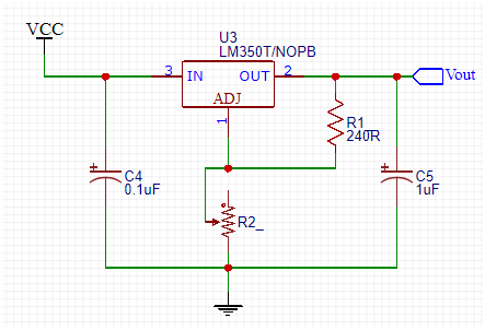
The Resistor R1 (should be 240R) and the potentiometer (can be upto 10k) together creates a potential difference at adjust pin which regulates the output pin accordingly. The formulae to calculate the Output voltage based on the value of resistors is
VOUT = 1.25 × (1 + (R2/R1)) + Iadj(R2)
Now, let’s verify this formula for the above circuit. The value of R1 is 240 ohms and the value of R2 (potentiometer) is 5000 because it is a 10k potentiometer placed at 50% (50/100 of 1000 is 5000). The value of Iadj will be 50uA always since the reference voltage is 1.205
Vout = 1.25 × (1 + (5000/240)) + (50*10^-6)(5000)
= 29.9V
The same formula can also be used to calculate the value of resistor for you required output voltage. Once easy way to do this, is to use this online calculator to randomly substitute the value of resistors you have and check which output voltage you will get.
Applications
- Used for Positive voltage regulations
- Variable power supply
- Current limiting circuits
- Reverse polarity circuits
- Commonly used in Desktop PC, DVD and other consumer products
- Used in motor control circuits
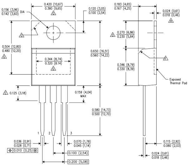
2D – Model of LM350 (TO-220)