CD4060 14-Stage Binary Counter IC
The IC CD4060 is a 14-bit Binary Counter IC from Texas Instruments. It has 12 output pins ranging from Q1 to Q14 excluding Q2 and Q3.
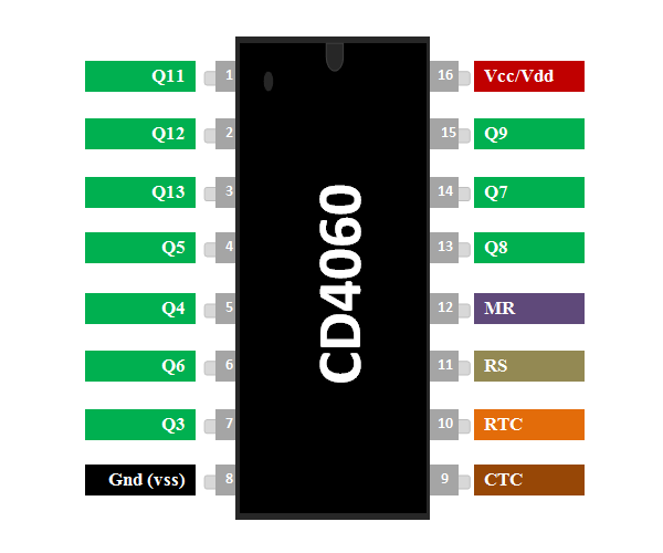
Pin Configuration
|
Pin Number |
Pin Name |
Description |
|
7,5,4,6,14,13,15,1,2,3 |
Q3, Q4, Q5, Q6, Q7, Q8, Q9, Q11, Q12, A13 |
Output pins of the Binary counter |
|
11 |
RS |
Clock Input Pin for setting clock frequency |
|
12 |
MR |
Master Reset |
|
9 |
CEXT/ |
External Capacitor to set clock frequency |
|
10 |
REXT/ |
External Resistor to set clock frequency |
|
8 |
Vss/Ground |
Connected to ground of the system |
|
16 |
Vdd |
Supply Voltage |
Features
- 14-bit Binary Counter/Divider
- Counting range: 0 to 16383 (In decimal)
- Operating Voltage: 3V to 18V
- Nominal Voltage: 5V, 10V, 15V
- Source current, sink current details are given in datasheet below.
- Maximum Clock Frequency: 30MHz at 15V
- Reset Propagation Delay: 25ns at 5V
- Available in 16-pin PDIP, CDIP,SOIC, TSSOP packages
Note: Complete Technical Details can be found at the CD4060 datasheet given at the end of this page.
Alternatives Binary Counters
CD4024B(7-bit), CD4024B(12-bit)
CD4060 Equivalents
Where to use CD4060 IC
The IC CD4060 is a 14-bit Binary Counter IC from Texas Instruments. It has 12 output pins ranging from Q1 to Q14 excluding Q2 and Q3. When an Input clock pulse is given to the pin for each pulse the binary value gets incremented from 00 0000 0000 0000 to 11 1111 1111 1111 which is equivalent for 0 to 16383 in decimal.
This behavior of the IC can be used to build counters and Dividers, also it is very commonly used for timing related applications. So if you are looking for a 14-bit binary counter which can be incremented through a clock pulse then this IC might be of interest to you.
How to use a CD4060 Binary Counter
Using the CD4060 binary counter IC is pretty simple. Just power the IC though the Vss and Ground pins, it has a wide operating voltage from 3V to 18V, but typically 5V is used. The most important step is setting your clock frequency. The CD4060 has an internal clock oscillator which can be set by using an external resistor (R1) and an external capacitor (C1) as shown in the circuit below.
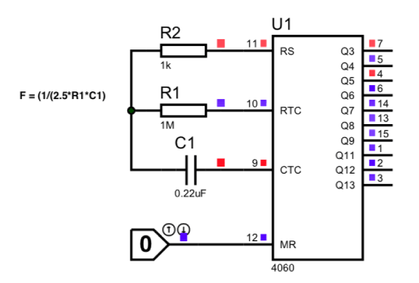
The formula to set the clock frequency is given is F= 1 / (2.5*R1*C1). Where the unit of F is Hz, R and C is ohms and farads respectively. In our case we have selected a value of 1MΩ for R1 and 0.22uF for the capacitor C1 so the resulting frequency will be
F = 1 / (2.5*1000000*0.00000022)
Fosc = 1.8Hz
Similarly by varying the values of R1 and C1 we can obtain clock pulses of different frequency. Once we get the clock pulse we can calculate the time using the below formulae.
T = 2n/Fosc
Where Fosc is the frequency of the oscillator that we just calculated and n is the output number. For example if we want to find the time during which the output Q5 will be high then the value of n will be 5. In that case
T = 25/1.8 = 32/1.8 = 17.7
T = 17.7 seconds
Meaning the output Q5 will go high after 17.7 seconds from resetting the Counter IC. The complete CD4060 working can be found in the Video linked below.
Applications
- Used for creating long timing period
- Astable frequency divider or counter circuit
- Timing related applications
- Used in project where Microcontrollers should be avoided
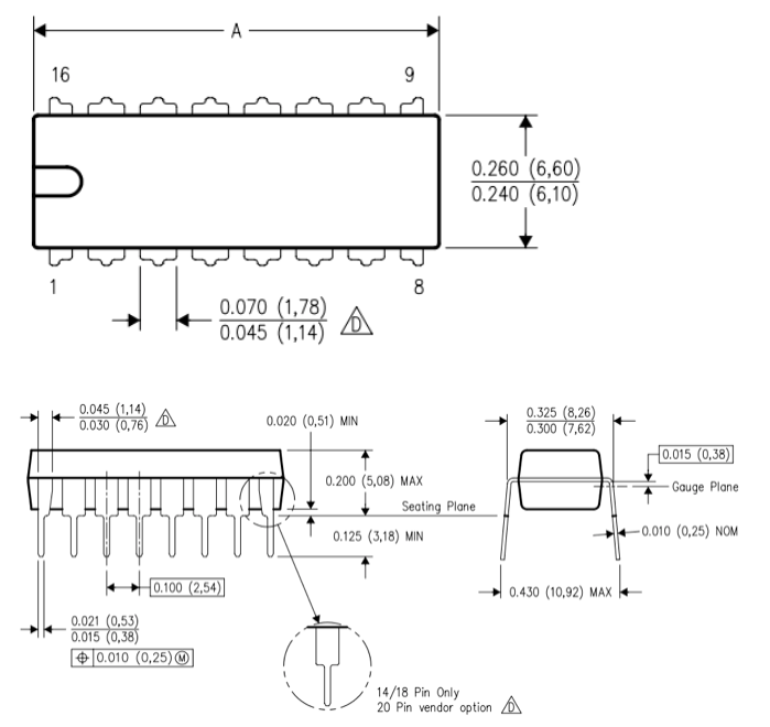
2D Model of CD4060 (PDIP)