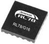
CD4017 IC
CD4017 is a versatile decade counter/divider IC with 10 decoded outputs, suitable for various counting applications and LED projects
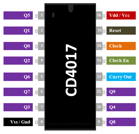
CD4017 Pin Configuration
Here is the pin configuration for the CD4017 IC which correlates with the CD4017 pin diagram above.
|
Pin Number |
Pin Name |
Description |
|
1 to 7 and 9,10,11 |
Output pins Q0 to Q9 |
These are the 10 output pins on which the counting occurs, they are not in order hence verify pin diagram above |
|
8 |
Vss or Ground |
Connected to the Ground of the circuit |
|
12 |
Carry Out (CO) |
This pin goes high after the IC counts from 1 to 10. This is used as carry while counting. |
|
13 |
Clock Enable (EN) |
This is an input which when made high will hold the count at the current state |
|
14 |
Clock |
The counting happens when this clock pulse goes high , this pin is normally connected to 555 timer or other uC to produce a pulse |
|
15 |
Resets |
As the name suggests this pin resets the count back to 1 |
|
16 |
Vdd / Vcc |
Connects to the supply voltage typically +5V |
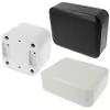
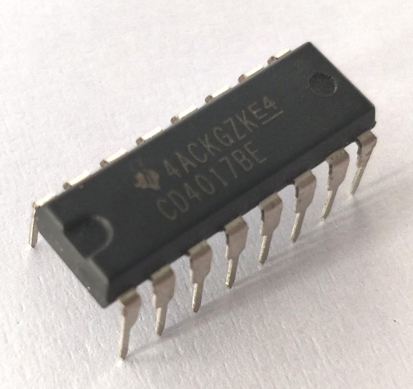
CD4017 Packages types
The CD-4017 is available in both through-hole and SMD packages. The through-hole packages include PDIP-16 and CDIP-16, while the SMD packages include SOIC-16, SOP-16 and TSSOP-16. More details about these packages can be found in the CD4017 IC datasheet attached at the end. Each package may have a different at the end of the part number. If you have ever wonderd whats the difference bet ween CD4017 or CD4017B or CD4017BE, essentially the same decade counter/divider IC. While the CS4017 is a generic name the CD4017BE indicates its package as PDIP.
Features of CD4017
- High speed 16 pin CMOS Decade counter
- Supports 10 decoded outputs
- Wide supply voltage range from 3V to 15V, typically +5V
- TTL compatible
- Maximum Clock Frequency: 5.5Mhz
- Available in 16-pin PDIP, GDIP, PDSO packages
Note: Complete Technical Details can be found in the CD4017 datasheet given at the end of this page.
CD4017 Equivalent Counters
IC4040, IC4060, IC4022
Where to use CD4017 IC
The IC CD4017 is used for counting applications, it has the capability to turn on 10 outputs sequentially in a pre-defined time and reset the count or hold it when required. It also has the capability to indicate the status of counting using Carry pin. This is commonly used for Led chasers and other logical output projects, so if you are looking for an sequential decoded counting IC that can count up to 10 then this IC will be your right choice
How to use a CD4017 IC
The IC can work from 3V to 15V, but normally powered with +5V to the Vdd/Vcc pin and the Ground/Vss pin is connected to ground. We have 10 output pins ranging from Q0 to Q9, these pins can be connected to any load but we are using LEDs here as shown in the circuit below.
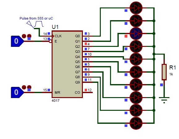
This IC will increment the count from 0 to 9 (Q0 to Q9) each time it senses a high pulse from the clock pin (pin 14). So we need a clock source to keep this IC ticking, this clock source can be a simple Timer circuit that could generate pulse or a microcontroller like Arduino, PIC, etc. to generate our custom pulse using I/O pins. To use the IC 4017 all we have to do is provide a HIGH pulse to the Clock pin. With each pulse t will count from 0 to 9. After 9 it will reset back to 0 and will continue to count. If we want to hold the value regardless of the clock pulse we should pull the enable pin High. and if we want to manually reset, we should pull the reset pin to High. For normal operation, don’t forget to pull these pin low. Here is a simple animation demonstrating the same.
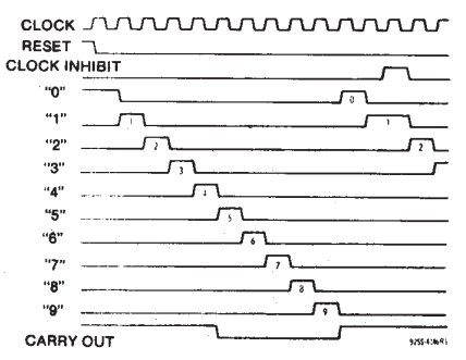
The output changes sequentially from Q0 to Q9 for every high pulse from the Clock pin, but this sequence can be interrupted by two pins. They are the Clock Enable (pin 13) and Reset (pin 15) pins. These pins are held low (0V/grounded) by default, but when the Clock Enable pin is made high the counting pauses. For example if the count was at pin Q3 when the Clock enable pin was made high, then the count will pause at pin Q3 irrespective of any high pulses from clock and will continue incrementing only when Clock Enable is made low again. Similarly, if the reset pin is made high. The count will reset itself back to Q0 and will stay there until Q0 is made low again.
We have another pin called the carry out pin (12th pin), this pin will stay low (0V) by default. But when the IC completes counting up to 10, the pin will go high and will remain high till it counts till 5, when its 5 it will go down (0V) and turn on again when it reaches 10.
CD4017 Working
As we know CD4017 is a 16-pin CMOS decade counter/ Divider. It takes the clock signal from the clock input and turns on the 10 output in sequence, each time when it receives clock input pulses. Initially, when power is applied, the CD4017 is typically reset to output 0. With each rising edge of the clock input, the output advances to the next stage. For example, if output 0 is high, and a clock pulse arrives, output 0 goes low, and output 1 goes high. This continues for each clock pulse. When output 9 goes high (after 9 clock pulses), it resets back to output 0, and the cycle continues. If you want to reset the counter at any point, you can apply a logic high to the RESET pin. The Carry Out pin can be used to extend the counting sequence or trigger other events when the count reaches 10.The timing diagram of the IC indicating the state of Output pins and Carry pin for every high pulse signal is shown below.
Applications
- Used in LED matrix, LED chaser and other LED projects
- Binary counter or Binary decoder
- Can be used for divide by N counting
- Remote metering, automotive, medical electronics
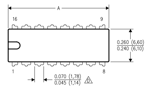
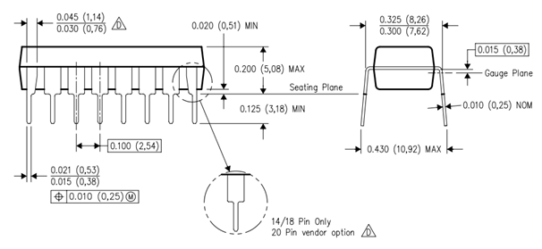
2D Model of CD4017 (PDIP)